Ta ble of Contents
ii
P7225 2.5 GHz 10X Active Probe User Manua l
List of Figures
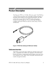
Figure 1: P7225 Probe featuring the TekConnect Interface 1
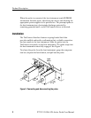
Figure 2: Connecting and disconnecting the probe 2.......
Figure 3: Probe functional check connections 15...........
Figure 4: Dynamic and offset limitations 18...............
Figure 5: Typical effects of using a probe tip adapter 21.....
Figure 6: Waveform distortion from ground l ead length 22..
Figure 7: Ground lead equivalent circuit 23...............
Figure 8: Low-inductance grounding 25...................
Figure 9: Using a SureFoot adapter for grounding 26.......
Figure 10: Using a push-in probe tip as a test point 27.......
Figure 1 1: Typical input impedance and phase versus
frequency 31.......................................
Figure 12: Typical bandwidth 32.........................
Figure 13: Probe head and c ompe nsation box dimensions 33.
Figure 14: P7225 replaceable parts 39....................
Figure 15: P7225 standard accessories 40.................
Figure 16: P7225 optional accessories 42..................


