TDS 520A, 524A, 540A, & 544A User Manual
Probe Accessories
The probe you use and how you connect it to a signal source affect the
oscilloscope acquisition of the waveform record. Two important factors are
ground lead inductance (introduced by the probe) and the physical layout of
your circuit and component devices.
For an amplitude measurement to be meaningful, you must give the measure-
ment some point of reference. The probe offers you the capability of referenc-
ing the voltage at its tip to ground. To make your measurement as accurate
as possible, the probe ground lead should be connected to the ground refer-
ence.
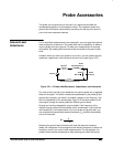
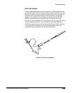
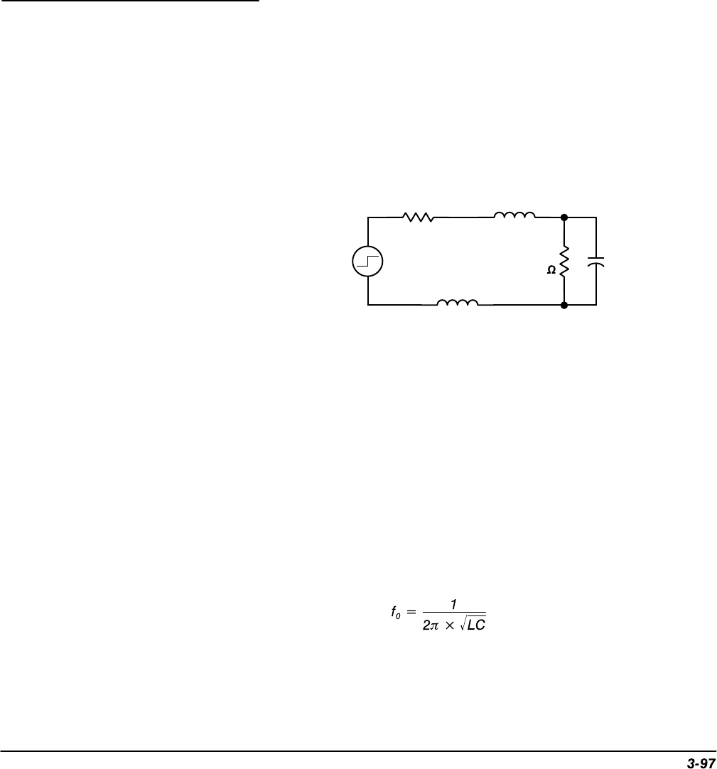
However, when you touch your probe tip to a circuit, you are introducing new
resistance, capacitance, and inductance into the circuit (see Figure 3-51).
V
source
R
source
Probe
R
in 10 M
Probe
10.0 pF
Probe
Tip Inductance L
t
Ground Lead Inductance L
gl
Figure 3-51: A Probe Adds Resistance, Capacitance, and Inductance
For most circuits, the high input resistance of a passive probe has a negligible
effect on the signal. The series inductances represented by the probe tip and
ground lead, however, can result in a parasitic resonant circuit that may “ring”
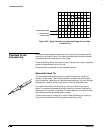
within the bandwidth of the oscilloscope. Figure 3-52 shows the effect of the
same signal through the same probe with different ground leads.
Ringing and rise time degradation may be hidden if the frequency of the
induced ringing is beyond the bandwidth of the oscilloscope. If you know the
self-inductance (
L
) and capacitance (
C
) of your probe and ground lead, you
can calculate the approximate resonant frequency (f
0
) at which that parasitic
circuit will resonate:
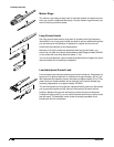
Reducing the ground lead inductance will raise the resonant frequency.
Ideally, the inductance is low enough that the resulting frequency is above the
frequency at which you want to take measurements. For that purpose, the
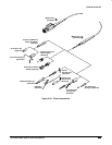
probes include several accessories to help reduce ground lead inductance.
Ground Lead
Inductance


