


Page 32 of 77 SCW Series Central Chilling Stations
4-11 Control Nozzle
All SCW Series chilling station evaporators have two control
nozzles. The flow switch, freezestat, and flush port are located in
the control nozzle. Pressure gages are mounted in the control
nozzles to aid in achieving proper flow through the evaporator and
balancing flows.
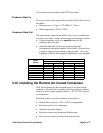
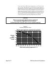
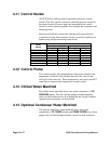
Pressure drop between evaporator entering water pressure and
evaporator leaving water pressure can be converted to gallons per
minute using the pressure drop charts below.
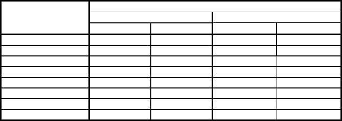
Water Side Pressure Drop
Condenser (each) Evaporator (each)
Model
Number
Flow (gpm) PD (psi) Flow (gpm) PD (psi)
SCWW/R60 91 4.0 72 5.3
SCWW/R75 102 4.7 90 4.5
SCWW/R90 117 4.4 107 5.6
SCWW/R100 150 5.5 123 3.9
SCWWR115 166 4.3 140 3.0
SCWW/R145 196 4.1 175 4.8
SCWW/R165 219 4.1 200 4.6
SCWW/R195 278 4.7 232 6.0
4-12 Control Probe
Two control probes sense temperatures. One probe measures the
temperature of the hot well and the other does the same for the
cold well of the reservoir. These temperatures are used by the PLC
controller to sequence the compressors, based on load.
4-13 Chilled Water Manifold
The chilled water manifold allows one-point connections of TO
PROCESS
piping. The Sch. 40 steel piping includes butterfly
valves at each evaporator for flow balancing and circuit isolation;
optional pressure gauges can be installed.
4-14 Optional Condenser Water Manifold
The optional condenser water manifold allows one-point
connection of
TO TOWER (drain) and FROM TOWER (city water)
piping. Sch. 40 steel include butterfly valves for each condenser.