


SCW Series Central Chilling Stations Page 29 of 77
4-5 Chilled Water Circuit
If your central chilling station is equipped with the optional
integral pump tank, make the process cooling water supply
connection at the P1 manifold at the left side of the pump tank at
the exposed connection. Bring the process cooling water return
connection to the
Hot well of the tank on the right side at the
flanged connection.
Warm coolant (water and ethylene glycol mixture) returns from the
process to the tank, then gets pumped through the evaporator
where it is cooled. The coolant flows to the process and returns to
repeat the cycle.
4-6 Refrigeration Circuit
• SCW Series chilling station air- and water-cooled unit
refrigeration cycles differ only in the way the compressed gas
is condensed to a liquid.
• Liquid refrigerant from the condenser passes through a shut-off
valve into a filter/dryer.
• The refrigerant then passes through the sight glass and solenoid
valves into the thermal expansion valve which regulates flow;
the valve lowers pressure and boiling point. Heat from the fluid
causes the refrigerant to boil off into a vapor.
• The refrigerant vapor flows through the suction line back into
the compressor.
• The refrigerant gives up heat as it re-condenses to a liquid in
the condenser.
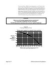
4-7 Freezestat Control
The freezestat shuts down the compressor if the chilled water
temperature approaches the freezing point. The chilled water pump
on the system will continue to run. It is factory-set at 40°F (4ºC) or
10°F (6ºC) below the rated capacity operating temperature of 50°F
(10ºC).