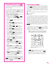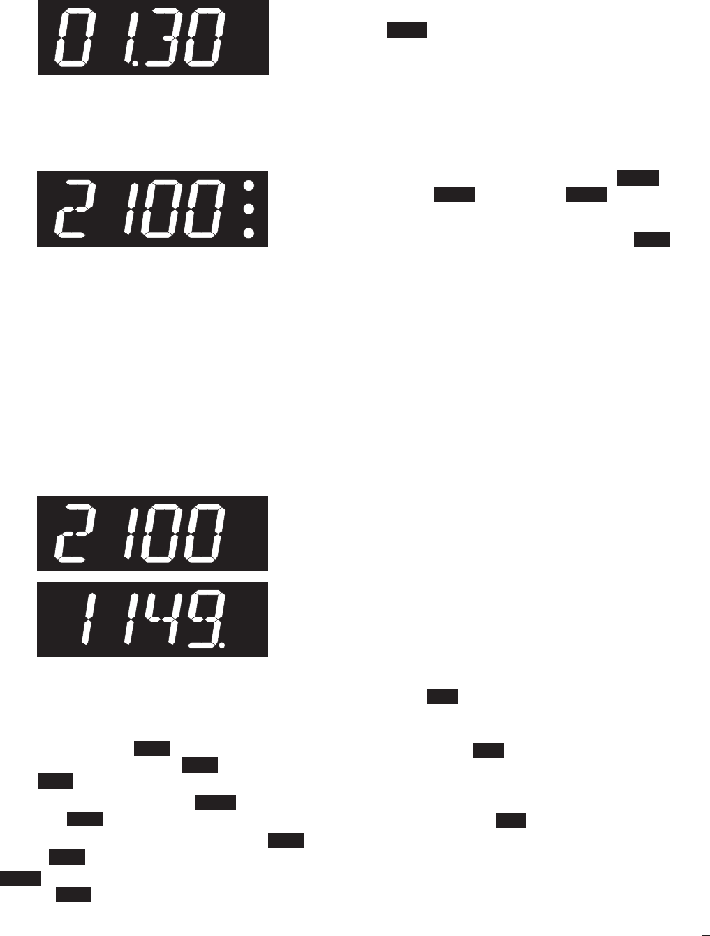
Display Lights
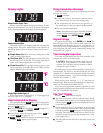
Single Center Light: Time
A lower center dot appears during time display. It sepa
-
rates hours fromminutes (i.e. 1 hour,30 minutes displays as
01.30). During temperature display, the dot disappears.
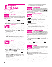
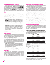
Power Output Lights
The Sentry turns on the heating elements intermittently
through relays. The power output lights in the right side of
the display appear when the Sentry sends power to the re
-
lay(s).
■
Single Zone Kiln When the Sentry sends power to the
relays, all three lights appear.
■
Two Zone Kiln The top light shows power to the relay
for the top section of the kiln. The bottom light shows
power to the bottom. Ignore the center light.
■
Three Zone Kiln The top light indicates power to the
top section relay, the middle light to the middle section,
and the bottom light to the bottom.
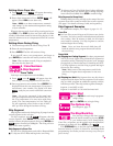
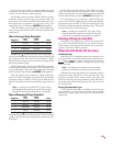
Single Right-Hand Light: °C
When temperature is displayed in °C, a light appears in
the lower right. In °F it disappears.
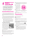
How to Get IdLE to Display
The controller displays IdLE when you first apply power
to the kiln. Operations begin from IdLE . You can’t fire the
kiln until IdLE appears.
■
If you press STOP during a firing, AbRT will appear. To
get back to IdLE , press ENTER.
■
If the display shows an error message such as FAIL in
-
stead of IdLE , see pages 22 - 23.
■
CPLT (firing completed) appears at the end of a firing.
To make IdLE appear, press any key.
Firing Completion Message
When the firing has completed, four messages will cycle
one after the other:
1 CPLT (complete)
2 Firing time in hours and minutes (amount shown
does not include Cone-Fire slow cooling time)
3 The temperature the kiln fired to in Cone-Fire, or
the temperature of the last segment in Ramp-Hold
4 The current kiln temperature
Note: If the alarm (see page 6) sounded, and then
the kiln fired to completion, you will see ALAR in
-
stead of CPLT . Press ENTER. CPLT will appear.
Repeat Firings
To repeat the last firing, press ENTER from IdLE . The
kiln will begin firing. This works in both Cone-Fire and
Ramp-Hold. But first, make sure you are repeating the cor
-
rect firing by using “Program Review” (see page 6). For re
-
peat firings that you don’t want to inadvertently change, see
“Program Lock,” page 20.
Thermocouple Inspection
The small rod protruding into the firing chamber is the
temperature sensor, or thermocouple.
CAUTION: Bumping the thermocouple can push
it out of the firing chamber. This could cause an
overfire! The controller does not contain an alarm
to detect this type of failure.
Thermocouples come in different widths. The wider the
thermocouple, the farther it should extend into the firing
chamber. A ¼” diameter thermocouple should extend into
thefiring chamberabout 1”.A 1/8”thermocoupleshould ex-
tend into the chamber ½” - 5/8”.
Keep shelves, posts and ware 1” - 1 ½” away from the
thermocouple. Keep an extra thermocouple on hand, espe
-
cially if you fire hotter than 2000°F/1093°C.
If you are using a portable, separate controller, you will
need to install the thermocouple onto the kiln. See the sepa
-
rate TnF 2 installation instructions.
The “LId” Display
Reasons LId appears in the display:
■
The kiln is equipped with the optional safety switch.
(The switch turns offpower to the elements when the lid
or dooris open.) LId appears in thedisplay while the lid
is open during firing.
■
On the back of the Sentry circuit board, at the top right
side, is a small two-pinterminal. If the connector on that
terminal is missing, LId will appear in the display dur
-
ing firing. The elements will not turn on. (If the two-pin
connector is missing, you can buy another from a com
-
puter supply store.)
■
The safety lidswitch is defective or thesafety switch wire
is broken.
5
°F
°C


