


Quantum 610 Series www.pridemobility.com 23
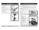
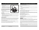
WIRE TIES
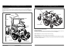
Figure 13. Controller Routed on a Contour Seat
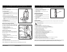
Power Seat Option Installation
Your power chair may be equipped with the power seat
option. While the seat itself may be any one of the styles
offered for this model, the way the seat base attaches to the
power base is different.
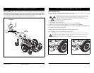
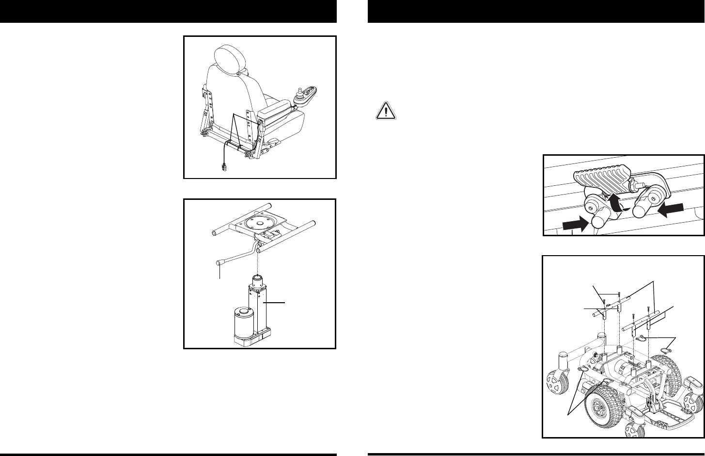
To install the power seat:
l. Align the post on the bottom of the power seat base
over the hole in the power seat actuator.
2. Slide the post into the actuator and push the friction
lock lever forward.
3. Connect the power seat cable to the power base.
4. Tilt the seat back and slide the rear extension onto the
power seat base.
5. Lower the front extrusion onto the power seat base
until the seat locks into place.
6. Flip down the seat latch safety.
7. Install the controller.
NOTE: Refer to V. “Comfort Adjustments” for more
information on controller installation and adjustment.
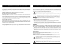
Figure 14. Power Seat Actuator
IV. ASSEMBLY
FRICTION LOCK
LEVER
POWER SEAT
ACTUATOR
24 www.pridemobility.com Quantum 610 Series
V. COMFORT ADJUSTMENTS
COMFORT ADJUSTMENTS
After becoming familiar with your power chair’s operation, you may find the need to make some adjustments to
increase your comfort, such as seat height and angle, armrest angle, foot platform height and angle, and controller
position. If your power chair is equipped with power positioning options, refer to the information supplied in
supplemental manuals or contact your Quantum Rehab Provider.
WARNING! The center of gravity of your power chair was factory set to a position that meets the
needs of the demographic majority of users. Your Quantum Rehab Provider has evaluated your
power chair and made any necessary adjustments to suit your specific requirements. Do not
change your seating configuration without first contacting Pride Mobility Products or your
Quantum Rehab Provider.
WARNING! Some power chair components are heavy. You may need assistance to lift or carry
them. Please refer to “Appendix I - Specifications” for specific component weights before you
disassemble the power chair.
WARNING! Remove the occupant from the power chair before making any adjustments.
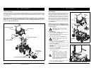
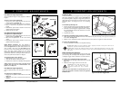
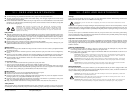
TRAPEZE BARS
RETAINING
CLIPS
SEAT POSTS
Figure 16. Seat Height Adjustment - Trapeze Bars
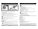
SCREWS
SEAT POSTS
RETAINING
CLIPS
You may need the following to make comfort adjust-
ments:
metric/standard socket set and ratchet
adjustable wrench
thread lock
Seat Height and Seat Angle Adjustment
You can change the seat height to one of four positions
in 1-in. (2.54-cm) increments by raising the front and
rear trapeze bars. If you raise or lower only one trapeze
bar (front or rear), you can also change the seat base
angle (dump).
To change the seat height:
1. Turn off the power to the controller.
2. Loosen the rear shroud fasteners and remove the rear
shroud. See figure 6.
3. Disconnect the controller connector(s) from the
power base. See figure 7.
4. Flip up the seat latch safety. See figure 15.
5. Squeeze the seat latch and release the seat from the
front trapeze bar. See figure 15.
6. Slide the seat forward and remove it from the power base.
7. Loosen the screws that attach the trapeze bars to the
seat posts. See figure 16.
8. Remove the retaining clips that secure the seat posts
to the power base. See figure 16.
9. Move the trapeze bars up or down to the desired
height.
10. Reinstall the retaining clips from step 8.
11. Remove each screw from the trapeze bars and apply
thread lock.
12. Reinstall each screw into the trapeze bars and
tighten.
13. Reinstall the seat and flip down the seat latch safety.
14. Reconnect the controller connector(s) to the power base.
15. Reinstall the rear shroud and tighten the fasteners.
Figure 15. Seat Height Adjustment - Seat Latch Safety