Quantum 610 Series www.pridemobility.com 21
SEAT INSTALLATION
SEAT HEIGHT/ANGLE ADJUSTMENT
FOOT PLATFORM HEIGHT/DEPTH ADJUSTMENT
FOOT PLATFORM
ANGLE ADJUSTMENT
INITIAL ASSEMBLY
Your power chair may require some assembly either before initial use or after transportation. It may also require
disassembly to make some comfort adjustments. Figure 10 details those parts of the power chair that are designed
to be disassembled and assembled by an end user or by a qualified caregiver before using the product or making
comfort adjustments.
NOTE: Any nylon insert lock nut removed during the disassembly or adjustment of the power chair must be
replaced with a new nut. Nylon insert lock nuts should not be reused as it may cause damage to the nylon insert,
resulting in a less secure fit. Replacement nylon insert lock nuts are available at local hardware stores or
through your Quantum Rehab Provider.
IV. ASSEMBLY
ARMREST ANGLE ADJUSTMENT
Figure 10. Quantum 610 Series Assembly View (Universal Mounting System Shown)
CONTROLLER POSITION
22 www.pridemobility.com Quantum 610 Series
IV. ASSEMBLY
Seat Installation
It may be necessary to install the seat either prior to
initial operation or after transporting your power chair.
Most seats are attached to the power base with the Uni-
versal Mounting System (UMS). The UMS consists of
universal parts that may be attached to any medium-
back or high-back seat, regardless of seat width or seat
depth. The two main components are aluminum extru-
sions mounted to the seat base. These extrusions attach
to a pair of trapeze bars that are mounted to the power
base. See figure 11.
NOTE: If your power chair is equipped with a Spe-
cialty Seat, Synergy Seat, or a TRU-Balance Power
Positioning System, refer to the information provided
in separate manuals.
WARNING! Do not pick up the seat
frame by the armrests. They are free to
pivot, and you may lose control of the
seat if they do so.
To install the seat:
1. Tilt the seat back and slide the rear extrusion onto
the rear trapeze bar. See figure 11.
2. Lower the front extrusion onto the front trapeze bar
until the seat locks into place.
3. Flip the seat latch safety down. See figure 11.
WARNING! Make sure the seat latch
safety is flipped down before using
your power chair.
4. Install the controller and route the harness to the
back of the power base. See figure 12.
5. Loosen the rear shroud fasteners and remove the
rear shroud. See figure 6.
6. Plug the controller connector into the power base.
See figure 7.
7. Reinstall the rear shroud and tighten the rear
shroud fasteners. See figure 6.
8. Route the controller harness so that it cannot be
pinched in the seat hinge.
MANDATORY! Prevent controller
harness damage! Use correct tie-down
points for controller harness. Avoid
routing the controller harness on the
outside of the armrest pad. Route the
harness under the armrest or toward the
inside of the armrest pad. Use correct
tie-down points for the controller
harness to prevent the harness from
getting caught in the drive tires, pinched
in the seat frame, or damaged when
passing through doorways.
9. Secure the controller harness to the armrest
receiver with wire ties. See figure 13.
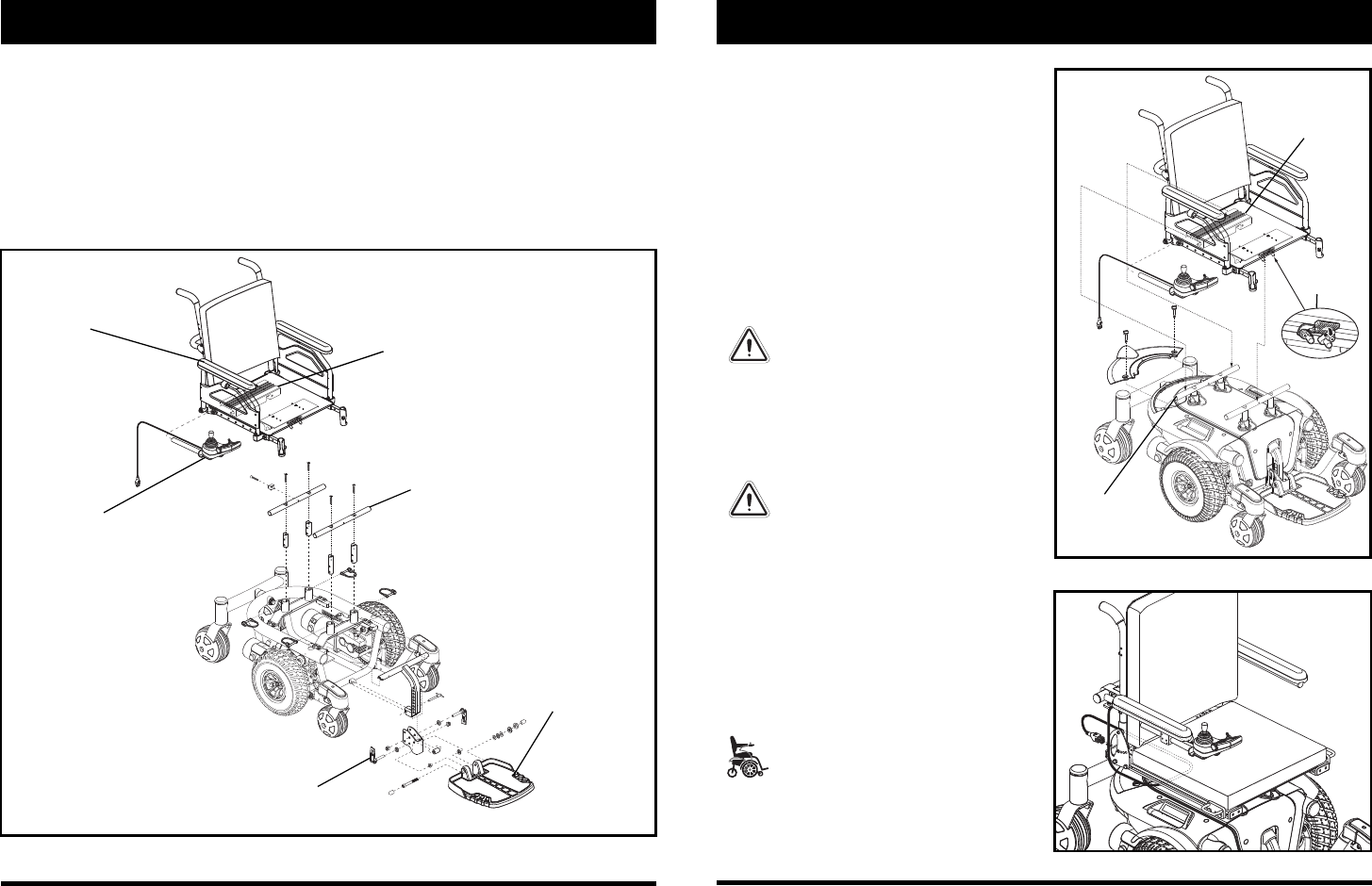
Figure 11. Universal Mounting System
Figure 12. Controller Routed on a Synergy Seat
REAR
EXTRUSION
REAR TRAPEZE
BAR


