


Quantum 610 Series www.pridemobility.com 17
III. YOUR POWER CHAIR
THE QUANTUM 610
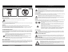
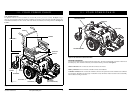
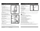
The Quantum 610 has two main assemblies: the seat assembly and the power base assembly. See figure 5. Typi-
cally, the seat assembly includes the armrests, seatback, and seat base. The power base assembly includes two
motor/brake assemblies, two drive wheels, four caster wheels, two batteries, and wiring harnesses. See figure 5,
6, and 7.
SEATBACK
REAR
SHROUD
DRIVE WHEEL
CASTER WHEEL
Figure 5. The Quantum 610 Series
POWER BASE
ASSEMBLY
SEAT ASSEMBLY
FRONT RIGGING
(FOOT PLATFORM SHOWN)
SEAT BASE
ARMRESTS
CONTROLLER
CASTER WHEEL
18 www.pridemobility.com Quantum 610 Series
III. YOUR POWER CHAIR
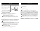
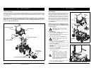
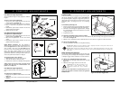
Electrical Components
The electrical components are located inside the power base. The main circuit breaker is located on the front of
the battery tray. The controller connector(s) are located inside the power base. See figure 7.
Motor Connectors: This is where the controller connects to the motors.
Battery Connector: This is where the controller connects to the batteries.
Controller Connector: This is where the controller connects to the power base. Each controller uses a different
type of harness. Regardless of which type of controller is used, the harness must be secured to the seat assembly
and not allowed to drag on the floor.
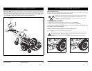
Figure 6. The Quantum 610 Series Power Base
MOTOR/BRAKE ASSEMBLY
REAR SHROUD FASTENER
TRAPEZE BARS
FRONT COVER