


Backpacker www.pridemobility.com 11
III. INSTALLATION
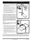
WARNING! Release the “DOWN” button when the lift platform touches the ground. Do not
allow the motor to run after the lift platform has touched the ground. Allowing the motor to
run will increase the pressure on the lift platform and may result in product or vehicle
damage.
Wiring Harness Installation
The wiring harness is approximately 25 ft. (7.62 meters) long and will accommodate most vehicles.
NOTE: You may wish to perform a practice run before installing the wiring harness. Route a piece of
light rope (equivalent to the gage of the wiring harness) along the anticipated path observing contact
points, potential rubbing/chafing points, and any sharp edges. Remove sharp edges with a fine grade
file, then treat the steel with a rust inhibitor or metal sealant.
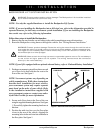
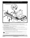
Follow these steps to route the Backpacker wiring harness:
1. Route the lift system wiring harness (starting at the lift) through the interior of the vehicle until you reach the
vehicle battery. See figure 5.
WARNING! Avoid routing the wire harness where it will interfere with or become pinched
by the securement system floor plates.
2. Conceal the harness behind or under the interior panels (there should be existing holes). Be certain that the
harness is protected with a rubber grommet when passing it through the metal panels and into the engine
compartment.
3. Inside the engine compartment, secure the harness to the firewall and the inner fender with plastic wire ties. Use
care not to cause abrasions to the wiring harness. It is important to secure the wiring harness at various points
along its run of the vehicle.
WARNING! Do not cut or shorten the wiring harness. If the harness is too long, coil the
excess wire and secure it with plastic wire ties.
4. Remove the 15-amp fuse from the wiring harness. See figure 5.
5. Connect the red wire to the positive (+) terminal and the black (grounding) wire to the negative (-) terminal
of the vehicle battery.
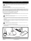
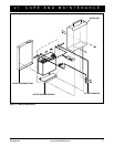
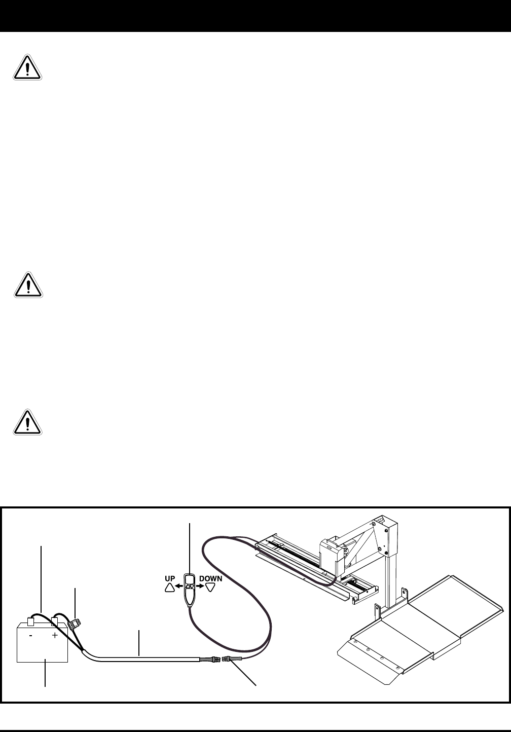
Figure 5. Wiring Harness Installation
VEHICLE BATTERY
WIRING HARNESS
HAND CONTROL
LIFT WIRING CONNECTION
FUSE
GROUNDING WIRE