42
www.pridemobility.com Quantum Jazzy 1400 Series Rev D May 04
5. Pull the wheel off the axle.
6. Remove the old tube from the pneumatic tire and replace it with a new tube.
7. Slide the wheel back onto the shaft.
8. Reinstall the drive wheel nut into the center hub and tighten.
9. Inflate the pneumatic tire to 35 psi.
Battery Replacement
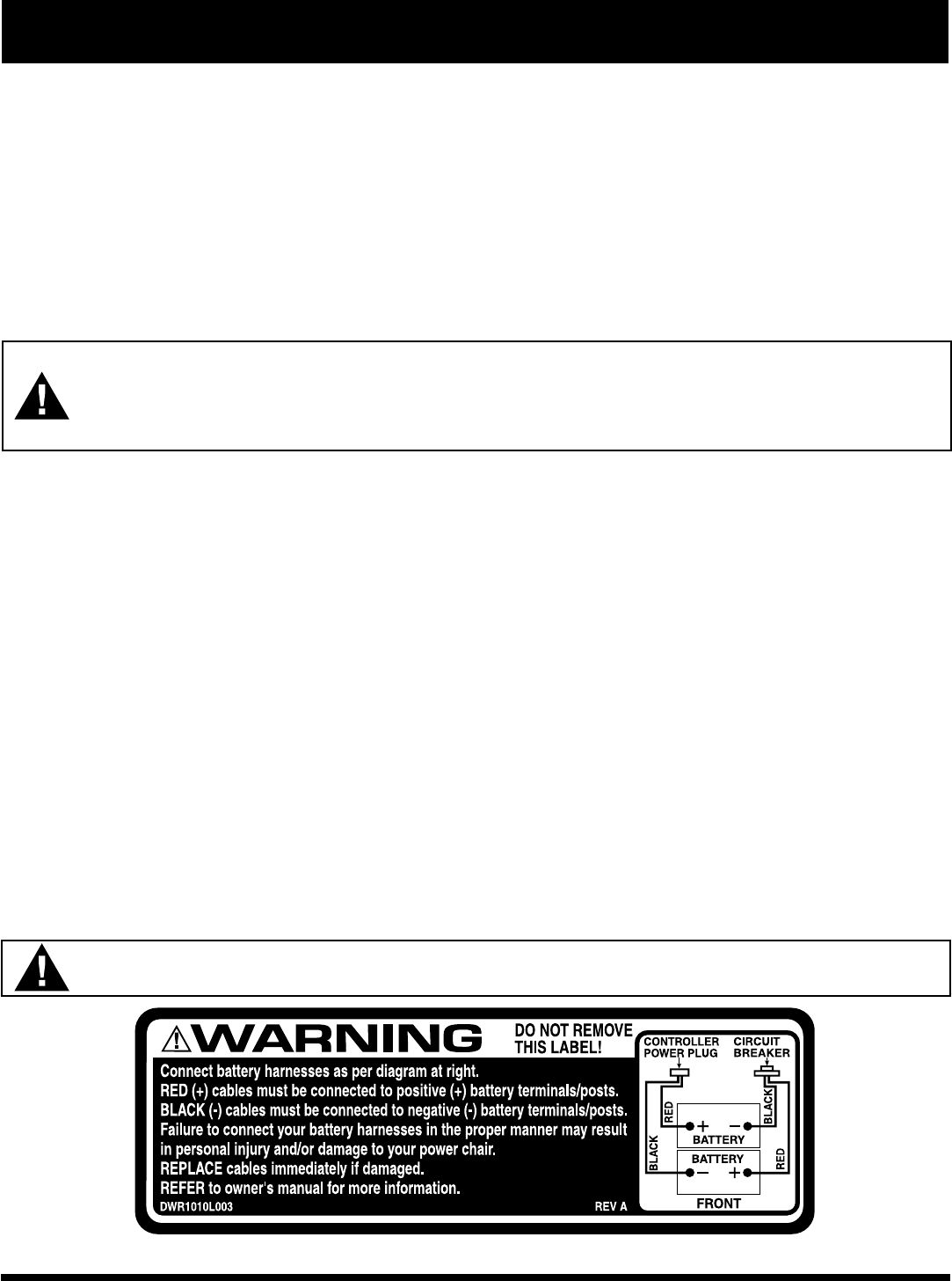
For battery specifications, see VI. Batteries and Charging. A diagram is printed on a decal located on the power chair frame
near the battery tray. See figure 24.
WARNING! Battery posts, terminals, and related accessories contain lead and lead compounds. Wear
goggles and gloves when handling batteries. Wash hands after handling.
WARNING! Power chair batteries are heavy. See specifications table. If you are unable to lift that much
weight, be sure to get help. Lifting beyond your capacity can result in personal injury.
To replace the batteries:
1. Turn the power off.
2. Make sure that the power chair is in drive mode. See IV. The Quantum Jazzy 1400 Series.
3. Unplug the connectors from the electronics tray.
4. Remove the seat. See V. Comfort Adjustments.
5. Remove the shroud.
6. Disconnect the wiring harnesses from the batteries.
7. Remove the batteries from the power base.
8. Place the new batteries in the power base. Make sure that the terminals are facing inwards. If the battery terminals are in the
middle of the batteries, then make sure that the positive terminal of the rear battery is facing the negative terminal of the
front battery on the left side. See figure 24.
9. Looking at the power base from the front, connect the red wire from the left side to the positive (+) terminal on the rear battery and
connect the black wire from the left side to the negative (-) terminal on the front battery.
10. Connect the red wire from the right side to the positive (+) terminal on the front battery and connect the black wire from the
right side to the negative (-) terminal on the rear battery.
11. Reinstall the shroud.
12. Reinstall the seat.
13. Plug in the connectors to the electronics tray.
VIII. CARE AND MAINTENANCE
WARNING! Make sure you tighten the fasteners so that the connections are secure.
Figure 24. 1400 Series Battery Wiring Diagram Label


