


20
www.pridemobility.com Quantum Jazzy 1400 Series Rev D May 04
V. COMFORT ADJUSTMENTS
COMFORT ADJUSTMENTS
After becoming familiar with your power chairs operation, you may find the need to make some adjustments to increase your
comfort, such as seat height and angle, armrest angle, footrest height and angle, and the controllers position. If your power
chair is equipped with a Synergy Seat or the TRU-Balance, refer to the information provided in separate manuals. If your power chair
is equipped with a medium back, a high back, or a reclining seat, refer to the following information.
WARNING! If your power chair was configured at your authorized Pride provider, please consult your
healthcare professional before changing the seat position or making any other adjustment. Some
adjustments may degrade your power chairs performance and safety by changing its center of gravity.
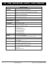
You may need the following to make comfort adjustments:
n metric/standard hex key set
n metric/standard socket set and ratchet
n adjustable wrench
Seat Height and Seat Angle Adjustment
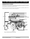
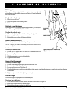
There are four seat towers that connect the seat to the power base. See
figures 3 and 8. You can change the seat height to one of three positions
in 1-in. increments by raising the seat towers. If you raise or lower only
one set of seat towers (front or rear), you can also change the seat base
angle. If your power chair is equipped with a power elevating seat, then
you change the seat height through the controller or a switch.
To change the seat height or seat angle:
1. Unplug the connector(s) from the electronics tray.
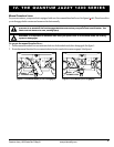
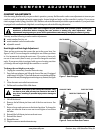
2. Press both seat plungers and lift up the front of the seat (if equipped
with footrest). See figure 7. Press both front seat tower latches and lift up
the front of the seat (elevating leg rests and swing-away footrest). See figure
8.
3. Allow the seat to rest on the front seat towers.
4. Pull the seat forward and lift it off the frame.
WARNING! Do not pick up the seat by the armrests. They
are free to pivot, and you may lose control of the seat if
they do so, resulting in personal injury and/or damage to
the chair.
5. Lift off the shroud.
6. Remove the ball detent pin from each of the four seat towers. See
figure 8.
7. Raise or lower each seat tower to the desired position. To change the
angle, set either the front or rear seat towers higher or lower than
the other.
8. Reinstall the ball detent pin into each seat tower.
9. Reinstall the shroud.
10. Reinstall the seat.
11. Plug the connectors into the electronics tray.
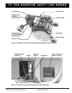
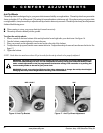
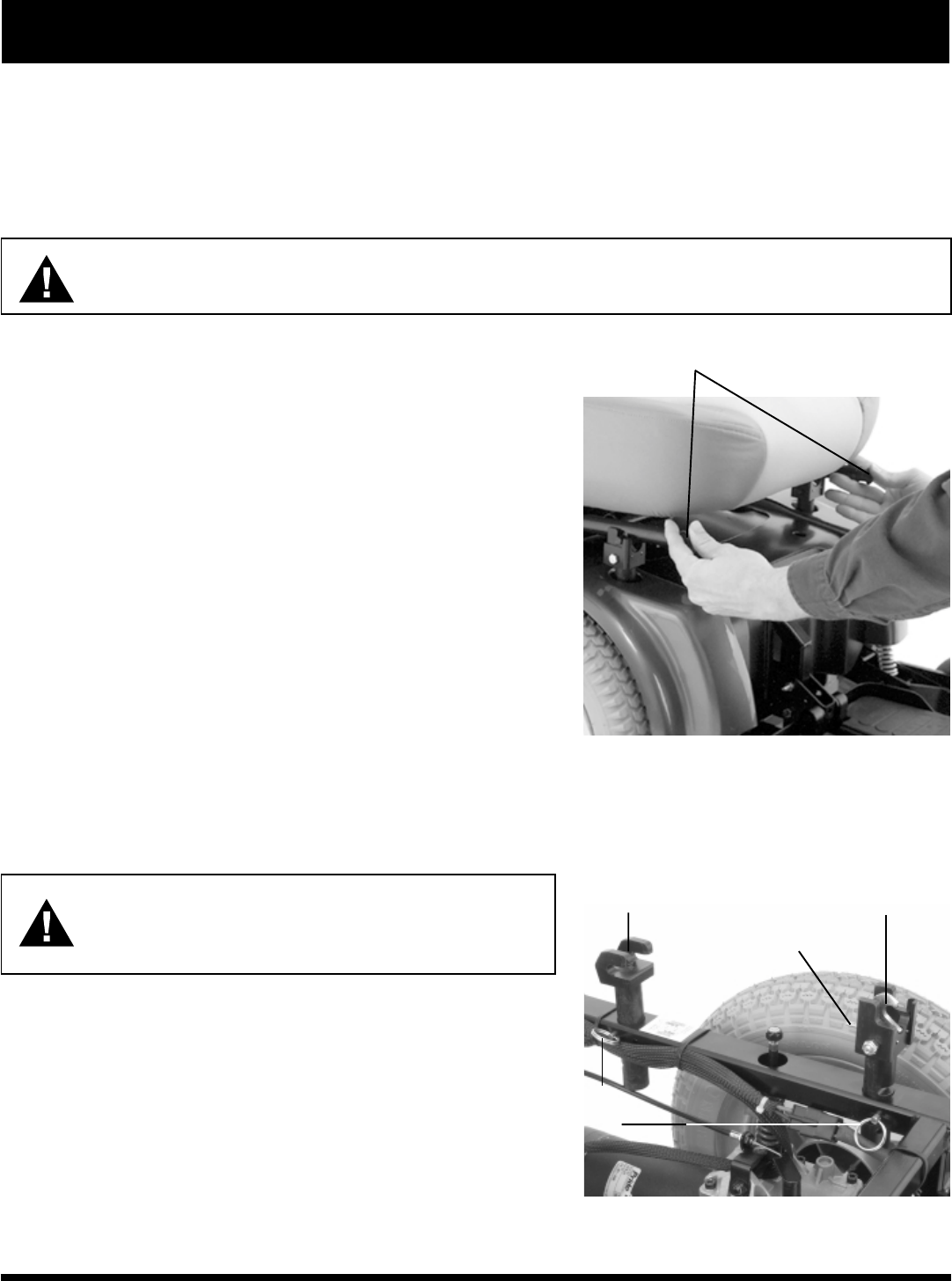
Figure 8. Front and Rear Seat Towers
REAR SEAT TOWER
FRONT SEAT TOWER
FRONT SEAT TOWER LATCH
BALL
DETENT
PINS
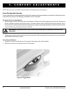
Figure 7. Seat Plungers
SEAT PLUNGERS