


Jet 7 www.pridemobility.com 21
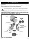
V. DISASSEMBLY
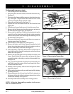
To disassemble your power chair:
1. Turn off the power to the controller.
2. Disconnect the controller connector from the electronics tray.
See figure 7.
3. Disconnect the charger inhibit connector from the electronics
tray. See figure 7. Squeeze the latch release levers on the
connector and pull it firmly from the socket.
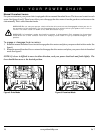
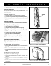
4. Flip up the seat latch safety. See figure 13.
5. Squeeze the seat latch and release the seat from the front
trapeze bar.
6. Slide the seat forward and remove it from the power base.
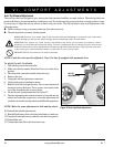
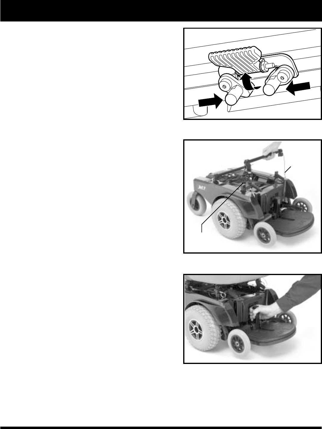
7. Remove the ball detent pins from the seat posts and remove
the front and rear trapeze bars. See figure 14.
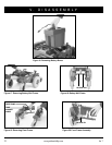
8. Remove the foot platform. Slide the mounting bracket up the
vertical bar of the front frame until the tabs on the mounting
bracket can be pulled forward through the matching slots in
the front frame. See figure 15.
9. Disconnect the battery connectors and the motor connectors
from the power base. See figure 6.
10. Lift and remove each battery box. See figure 16.
11. Remove the battery well frame. Squeeze together the latch
release levers that hang vertically down from the crossbar at
the rear of the battery well frame. See figure 17.
12. Lift up the battery well frame. Pull it to the rear of the chair to
release the front slots from the locating pins on the front frame
bottom bar. See figure 18.
13. Remove the left and right frame assemblies from the front
frame. Stand behind the power chair and grasp the frame
assembly handle on the side you wish to disassemble first.
See figure 19.
14. Use your hand and thumb to hold the front frame and press
and hold (toward the center of the front frame) the silver-
colored latch release lever.
15. Hold the frame assembly with one hand and push the frame
assembly outward.
16. Pull up on the front frame with your other hand until the latching
mechanism releases.
17. Keep pulling upward with your hand until the locating pin on
the bottom of that side of the front frame releases from its slot
in the frame assembly. See figure 20.
18. Carefully let the frame assembly tilt to a resting position.
NOTE: Follow the disassembly procedure in the reverse
order to assemble the unit.
Figure 13. Seat Latch Safety
SEAT POST
Figure 15. Removing the Footrest
BALL DETENT
PIN
Figure 14. Removing the Trapeze Bars