


Jet 7 www.pridemobility.com 17
III. YOUR POWER CHAIR
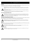
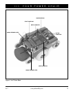
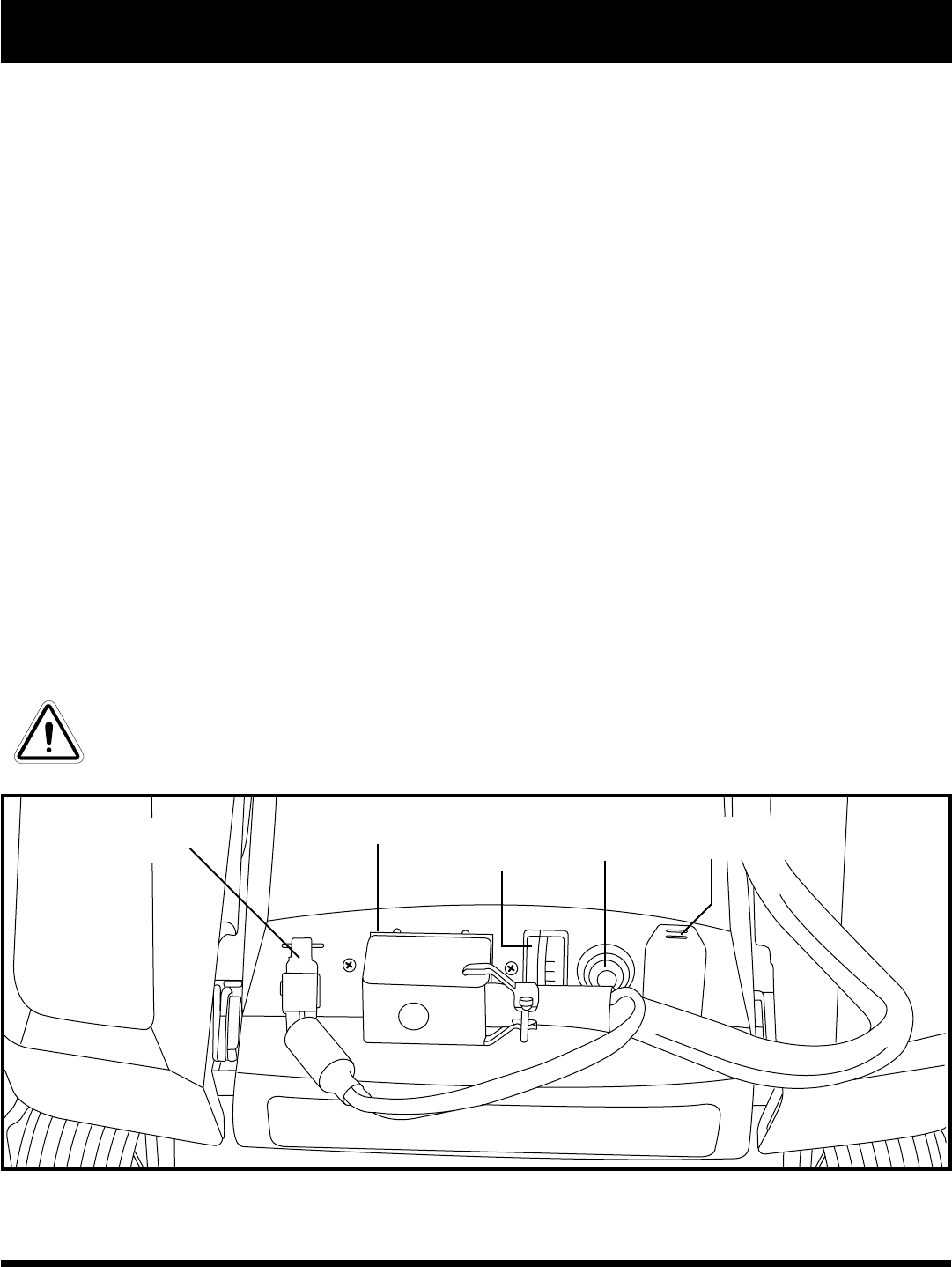
Electrical Components
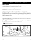
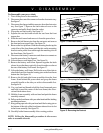
The electrical components are located on the power base. The battery connectors and motor connectors are located at the
rear of the power base. See figure 6. The ammeter, main circuit breaker, controller connector, charger power cord receptacle,
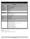
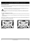
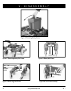
and the charger inhibit connector are located on the electronics tray. See figure 7.
Battery Connectors: These are where the battery boxes connect to the power base.
Motor Connectors: These are where the motors connect to the power base.
Ammeter: The ammeter displays the charger’s current output in amps. See VIII. “Batteries and Charging.”
Main Circuit Breaker: The main circuit breaker is a safety feature built into your power chair. When the batteries and the
motors are heavily strained (e.g., from excessive loads), the main circuit breaker trips to prevent damage to the motors and
the electronics. If the circuit trips, allow the power chair to “rest” for approximately one minute. Then, push in the circuit
breaker button, turn on the controller, and continue normal operation. If the main circuit breaker continues to trip repeatedly,
contact your authorized Pride Provider.
Controller Connector: This is where the controller connects to the batteries, motors, and motor brakes.
Charger Power Cord Receptacle: This is where the onboard battery charger cord plugs into the onboard battery
charger. See VIII. “Batteries and Charging.”
Charger Inhibit Connector: This is where the charger connects to the controller. This connector is coded with colored
dots. Make sure that you align the two colored dots before making the connection.
WARNING! Failure to properly align the connectors can result in damage to the controller, the
charger, and the connectors.
CONTROLLER CONNECTOR
AMMETER
MAIN CIRCUIT
BREAKER
Figure 7. Electronics Tray
CHARGER POWER
CORD RECEPTACLE
CHARGER INHIBIT
CONNECTOR