


26 www.pridemobility.com Jet 10 Ultra/RevA/Apr04
VI. COMFORT ADJUSTMENTS
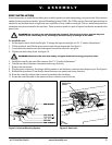
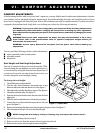
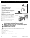
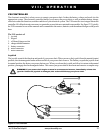
To rotate the ELRs:
1. Push in release lever A. See figure 20.
2. Rotate the ELRs.
To adjust the ELR angle:
1. Push down release lever B. See figure 20.
2. Move the leg rest to the desired angle.
To adjust the ELR length:
1. Remove the two adjustment screws from the side of each
leg rest extension. See figure 20.
2. Slide the leg rest up or down to the desired length.
3. Reinstall the two adjustment screws.
Anti-Tip Wheels
The anti-tip wheels are designed to give your power chair
increased stability on rough surfaces. The anti-tip wheels are
preset at the factory for smooth surfaces or indoor use only.
If you plan on using your power chair on rough surfaces, it
may be necessary to adjust the anti-tip wheels to better suit
your needs. The anti-tip wheels may need adjustment if the
following occurs:
n When coming to a stop, your power chair tips forward
excessively.
n The anti-tip wheels constantly rub the ground.
LEG REST
ADJUSTMENT
SCREWS
RELEASE LEVER B
Figure 20. Elevating Leg Rests
RELEASE LEVER A
WARNING! Consult your authorized Pride Provider before attempting to change the anti-tip wheel
height! Changing the anti-tip wheel height affects handling under acceleration!
WARNING! The higher you raise the anti-tip wheels, the more you increase your power chairs
tendency to tilt forward while decelerating. You can compensate for this by moving the seat
assembly farther to the back of your power chair.
PROHIBITED! Do not remove the anti-tip wheels.
NOTE: Each drive tire must be inflated to 35 psi (if equipped with pneumatic tires) and the user
must also be seated in the power chair in order to properly adjust the anti-tip wheels.
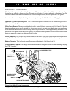
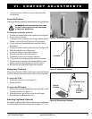
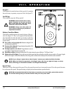
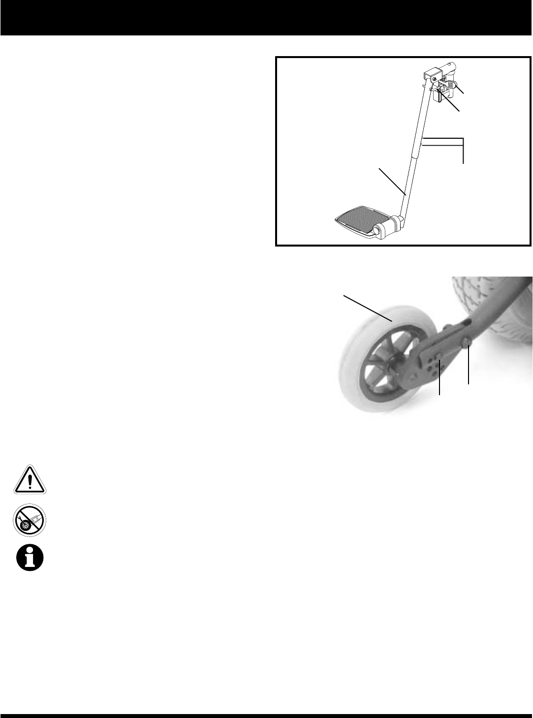
To adjust the anti-tip wheels:
1. Loosen bolt A. See figure 21.
2. Remove bolt B.
3. Raise or lower the anti-tip wheel. Each hole is 1/2-in. apart.
4. Reinstall bolt B.
5. Tighten bolt A.
6. Raise or lower the other anti-tip wheel so that it is at the same height.
LEG REST EXTENSION
Figure 21. Anti-Tip Wheel Assembly
ANTI-TIP WHEEL
A
B