


Jet 10 Ultra/RevA/Apr04 www.pridemobility.com 19
IV. THE JET 10 ULTRA
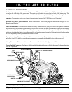
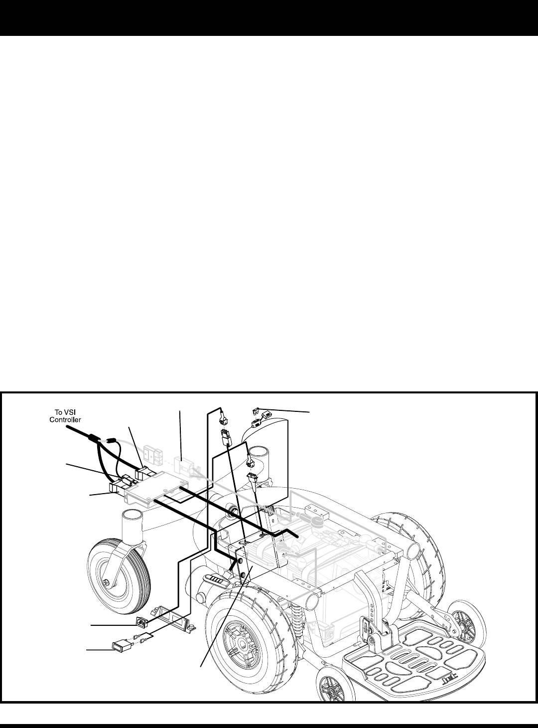
ELECTRICAL COMPONENTS
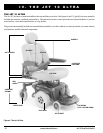
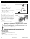
The electrical components are located on the power base. The ammeter and the onboard AC power cord receptacle are
located on the right side of the power base. The main circuit breaker is located on the front of the battery tray. The
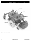
controller connector and the motor connectors are located on the power pod, inside the power base. See figure 6.
Ammeter: The ammeter displays the chargers current output in amps. See VII. Batteries and Charging.
Onboard AC Power Cord Receptacle: This is where the AC power cord plugs into the onboard charger. See VII
Batteries and Charging.
Main Circuit Breaker: The main circuit breaker is a safety feature built into your power chair. See figure 26. When the
batteries and the motors are heavily strained (e.g., from excessive loads), the main circuit breaker trips to prevent damage
to the motors and the electronics. If the circuit trips, allow your power chair to rest for approximately one minute. Next,
push in the circuit breaker button, turn on the controller, and continue normal operation. If the main circuit breaker contin-
ues to trip repeatedly, contact your authorized Pride Provider.
Motor Connectors: This is where the controller connects to the motors. The motor connectors are color-coded with red
and yellow labels. The label color on the motor connector corresponds with the label color on the power pod.
Battery Connector: This is where the controller connects to the batteries. See figures 6 and 26.
Charger Inhibit Connector: The charger inhibit enables the onboard charger to disable the controller during charging.
See VIII. Operation.
BATTERY CONNECTOR
MOTOR CONNECTOR
CHARGER INHIBIT
CONNECTOR
AMMETER
ONBOARD AC POWER
CORD RECEPTACLE
ONBOARD BATTERY CHARGER
CHARGER CIRCUIT FUSE
Figure 6. Jet 10 Ultra Electrical Components
MOTOR CONNECTOR