


Quantum 6000Z Series www.quantumrehab.com 29
V. COMFORT ADJUSTMENTS
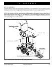
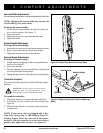
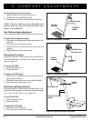
Figure 22. Underside of Foot Platform
NUT
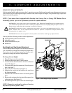
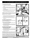
Figure 20. Foot Platform Adjustment
FOOT
PLATFORM
BRACKET
QUICK
RELEASE
FASTENERS
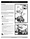
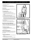
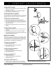
Figure 21. Quick Release Fastener Operation
LEVER (OPEN)
BOLT
NUT
CAM
UNCLAMPED
CLAMPED
LEVER (FULLY
CLOSED)
To change the controller position:
1. Turn off the power to the controller.
2. Loosen the rear shroud fasteners and remove the rear
shroud.
3. Unplug the controller connector from the power base.
4. Remove any wire ties securing the controller cable to
the armrest.
5. Loosen the mounting screws in the controller mounting
block. See figure 19.
6. Move the controller mounting block and controller to
the other armrest and tighten the mounting screws.
NOTE: For contour seats, loosen the setscrew on the
underside of both armrests, transfer the controller, and
tighten the setscrews. See figure 18.
7. Route the controller cable to the back of the power
base and plug in the controller. See figures 12 and 13.
8. Replace the rear shroud and tighten the fasteners.
9. Secure the controller cable to the armrest with wire ties.
See figure 13.
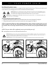
Foot Platform Height Adjustment
The foot platform height is easily adjusted to different heights
in 1/2-in. (1.27-cm) increments.
To raise or lower the foot platform:
1. Remove the quick release fasteners from the foot plat-
form bracket. See figure 20.
2. Raise or lower the foot platform to the desired height.
3. Reinstall the quick release fasteners into the foot plat-
form bracket and tighten.
Foot Platform Depth Adjustment
To adjust the foot platform depth:
1. Remove the quick release fasteners from the foot plat-
form bracket. See figure 20.
2. Move the foot platform in or out to the desired depth.
3. Reinstall the quick release fasteners into the foot plat-
form bracket and tighten.
Quick Release Fasteners: The foot platform is attached
to the power base with two quick release fasteners. See
figure 20. Each quick release fastener consists of a bolt, a
lever, and a nut. See figure 21. The lever has a cam on the
end that allows it to clamp into place. The quick release fas-
tener has two states: clamped and unclamped. When the
lever is open, the quick release fastener is unclamped. When
the lever is closed, the quick release fastener is clamped
.
SET SCREW