


Commander 400 www.pridemobility.com 9
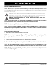
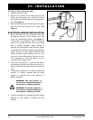
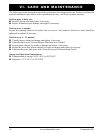
SECUREMENT BOLT
HOLES (UNDER SHROUD)
SECUREMENT
BOLT HOLE
SECUREMENT
BOLT HOLE
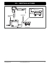
SECUREMENT
BOLTS
SECUREMENT
BOLTS
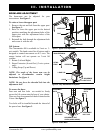
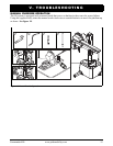
BOLT
NUT
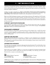
UPPER POST
BOOM ARM
LOWER POST
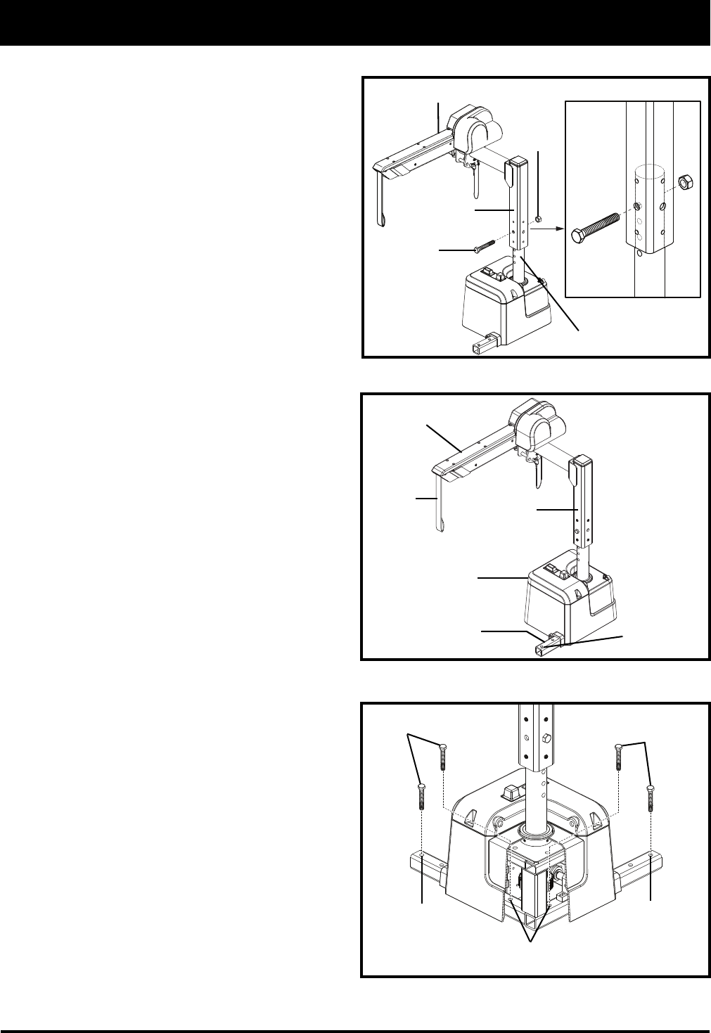
BOOM-ARM ADJUSTMENT
The boom-arm can be adjusted for your
convenience. See figure 1.
To raise or lower the upper post:
1. Remove the nut and bolt from the upper post.
See figure 1.
2. Raise or lower the upper post to the desired
position, matching the adjustment holes of the
upper post with the adjustment holes of the
lower post.
3. Reinstall the bolt through the adjustment hole
and secure it with the nut.
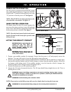
Lift System:
The Commander 400 is available in 2-axis or 3-
axis models. The hand control has 6 buttons and is
designed to control movement on all 3 axes. The
orange button will not operate on 2-axis lift
systems.
1. Rotate (Left and Right)
2. Boom Extension (In and Out) (3-axis system-
only).
3. Lifting Strap (Up and Down)
NOTE: The angle of the boom arm can be
adjusted to accommodate certain height
limitations. See figure 4.
NOTE: Do not force the threaded bolt into the
adjustment hole.
To secure the base:
Four nuts and four bolts are needed to firmly
secure the lift system onto the base of your choice.
There are four securement bolt holes located on the
L-base. See figure 2.
Two bolts will be installed beneath the shroud of
the power base. See figure 3.
III. INSTALLATION
Figure 2. Fully Assembled Lift System
L-BASE
L-BASE CAP
Figure 1. Upper Post Adjustment
Figure 3. Power Base
SECUREMENT
BOLT HOLE
UPPER POST
BOOM EXTENSION
LIFTING
STRAP