


9
Warning: The fiber type that is used with your thermometer is of a special type, and it is
recommended that you get ALL of your patch cords (also called extension cables) from Omega.
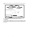
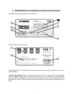
9) Analog output connector(s): There are a total of 1, 2 or 4 such connectors, one for each channel. Prior
to shipment, your FOB100 thermometer was factory set to one of the following configurations: 4-20mA or
0-10V output. The minimum analog output value corresponds to minus 100°C and the maximum analog
output value corresponds to 300°C. The thermometer normal range is from minus 80°C to 250°C, so a
minimum value indicates an under-range error; likewise, a maximum value indicates an over-range error
condition. If there is a sensor problem for a given channel, the analog output may take one of the following 3
states (refer to the RS-232 “o” command, Section 5.3):
a) It will toggle between the minimum and maximum values, at approximately 0.5 Hz, this indicates a
sensor problem for that channel (o0). This is the default setting; to change it, you will need to use the
RS-232 “o1” or “o2” command.
b) The analog output is forced to its maximum value (o1); this would indicate a “too-hot” situation.
c) The analog output is forced to its minimum value (o2); this would indicate a “too-cold” situation.
Warning: Do not connect any external voltages to these outputs; this may cause permanent
damage to the thermometer unit.
Note: If the unit is in “sleep” mode, the analog outputs will keep their values until the FOB100 acquires new
temperature values.
10) 18 Volts DC power connector: You can use a DC power supply from 14V to 28V; note that at 15V or
less, you will be unable to use more than one (1) 500Ω load at the analog output, for all current output
configurations. There is an internal fuse, to protect the system in case of electrical problems; this fuse is not
user changeable.