


7
3 FOB100
S
ERIES
T
HERMOMETER
H
ARDWARE
R
EFERENCE
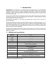
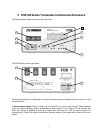
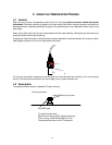
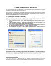
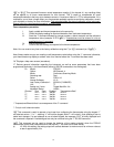
The following figure shows the thermometer front panel:
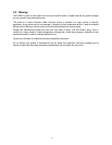
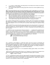
The FOB100 back panel is as follows:
The following presents a full description of the user interface as well as detailed instructions on how to use
the thermometer.
1) Sensor status light(s): There is a total of up to 4 lights for this, one for each channel. These indicators
inform you about the system status, as applicable to each channel. If any remains off, this indicates that
either that channel is disabled or there is a problem with that sensor (or with the optional patch cord
connected to it). Check if all optical connectors are correctly mated or if the sensor fiber (or patch cord) is not
broken.
7
6
1
10
2
3
9
8
4
5