


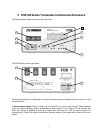

2) Serial communication status light:
RS-232 interface.
This is useful to confirm a good communication link with your PC when the FOB100
software package is used.
3) RS-
232 communication interface:
instrument. This DB-
9 connector uses the same pin
to-pin wired cable (
not a null modem cable
of the serial commands that are available.
4) 2 x 16 Display:
Under normal use, the display will show the temperature readings for the user selected
channels; the temperatures are displayed in either
information is displayed to guide the user in making the selections
5) FNCT and SET keys:
When the FNCT key is not activated; the display will show the temperatures for the
requested channels. The FNCT key allows the user to scroll through the menu items. All settings are kept in
permanent memory, until
changed again by the user, using either the keypad or a RS232 command.
This key allows users to scroll through the different options.
This key allows users to browse from field to another, for options that have many fields.
This key allows users to
set a value to the selected field.
The description of each of the menu items is:
1-
Sampling rate: Adjust the resolution of the display. In Fast mode, the instrument focuses on faster
response time. In Slow mode, the focus is on higher resolution; this is ach
4 temperature measurements, which tends to reduce the noise, but to increase the effective
response time. In Slow mode, the display shows gives temperatures in hundredths of degrees, while
in Fast mode the display is in tenths o
2-
Ch Enable Scan: Enable or disable the reading of a channel. Channels that are turned off are not
read, thus allowing the “on” channels to be read faster.
3- Temp. Unit: Enable
users to change the temperature unit of the instrument. The thermometer
continue to display temperatures using the newly selected unit.
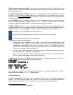
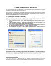
6) Power switch.
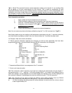
Make sure the FOB100
series of messages are displayed
(actual information may differ
FOB100
FOB100FOB100
FOB100
Single
SingleSingle
Single
Channel
ChannelChannel
Channel
www.omega
www.omegawww.omega
www.omega.com
.com.com
.com
Ver: 0.2.25
Ver: 0.2.25Ver: 0.2.25
Ver: 0.2.25
cal:
cal: cal:
cal: 06/11/14
06/11/1406/11/14
06/11/14
1
11
1
Then temperatures should then be displayed, assuming they are correctly connected, and so forth. If
temperatures are unreadable,
-----
7) Power status light.
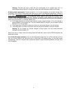
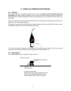
8) Sensor connector(s):
These are ST type connectors, mating to each of the 4 optical temperature
sensors. If you need to extend a sensor fiber, you should use optional patch cor
Omega
. For thermometers that have 1 or 2 channel(s), only 1 or 2 sensor c
1
This is the calibration date (format YY/MM/DD
8
2) Serial communication status light:
These indicators are directly connected to the Tx and
This is useful to confirm a good communication link with your PC when the FOB100
232 communication interface:
This port is used to configure and extract information for the
9 connector uses the same pin
-
out as a COM port on a PC computer. Use a simple pin
not a null modem cable
) to connect to a computer. See below for a complete description
of the serial commands that are available.
Under normal use, the display will show the temperature readings for the user selected
channels; the temperatures are displayed in either
o
C or
o
F. However, when the FNCT key is used,
information is displayed to guide the user in making the selections
(see item 5 below).
When the FNCT key is not activated; the display will show the temperatures for the
requested channels. The FNCT key allows the user to scroll through the menu items. All settings are kept in
changed again by the user, using either the keypad or a RS232 command.
This key allows users to scroll through the different options.
This key allows users to browse from field to another, for options that have many fields.
set a value to the selected field.
The description of each of the menu items is:
Sampling rate: Adjust the resolution of the display. In Fast mode, the instrument focuses on faster
response time. In Slow mode, the focus is on higher resolution; this is ach
ieved by averaging the last
4 temperature measurements, which tends to reduce the noise, but to increase the effective
response time. In Slow mode, the display shows gives temperatures in hundredths of degrees, while
in Fast mode the display is in tenths o
f degrees.
Ch Enable Scan: Enable or disable the reading of a channel. Channels that are turned off are not
read, thus allowing the “on” channels to be read faster.
users to change the temperature unit of the instrument. The thermometer
continue to display temperatures using the newly selected unit.
Make sure the FOB100
power supply module is connected and powered. At power on, a
(actual information may differ
):
Channel
ChannelChannel
Channel
1
11
1
Then temperatures should then be displayed, assuming they are correctly connected, and so forth. If
-----
will be displayed.
These are ST type connectors, mating to each of the 4 optical temperature
sensors. If you need to extend a sensor fiber, you should use optional patch cor
ds that are available from
. For thermometers that have 1 or 2 channel(s), only 1 or 2 sensor c
onnectors are used.
This is the calibration date (format YY/MM/DD
).
These indicators are directly connected to the Tx and
Rx lines of the
This is useful to confirm a good communication link with your PC when the FOB100
-SOFT
This port is used to configure and extract information for the
out as a COM port on a PC computer. Use a simple pin
-
) to connect to a computer. See below for a complete description
Under normal use, the display will show the temperature readings for the user selected
F. However, when the FNCT key is used,
When the FNCT key is not activated; the display will show the temperatures for the
requested channels. The FNCT key allows the user to scroll through the menu items. All settings are kept in
changed again by the user, using either the keypad or a RS232 command.
This key allows users to browse from field to another, for options that have many fields.
Sampling rate: Adjust the resolution of the display. In Fast mode, the instrument focuses on faster
ieved by averaging the last
4 temperature measurements, which tends to reduce the noise, but to increase the effective
response time. In Slow mode, the display shows gives temperatures in hundredths of degrees, while
Ch Enable Scan: Enable or disable the reading of a channel. Channels that are turned off are not
users to change the temperature unit of the instrument. The thermometer
will
power supply module is connected and powered. At power on, a
Then temperatures should then be displayed, assuming they are correctly connected, and so forth. If
These are ST type connectors, mating to each of the 4 optical temperature
ds that are available from
onnectors are used.