


14 The Tool Compensation
87
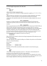
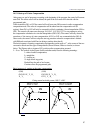
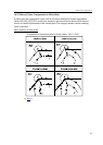
Fig. 14.5.1-1
14.5.1 Start up of Cutter Compensation
After power-on, end of program or resetting to the beginning of the program, the control will assume
state G40. The offset vector will be deleted, the path of the tool center will coincide with the
programmed path.
Under instruction G41 or G42 the control will exit from state G40 to enter in radius-compensation
computation mode. The value of compensation will be taken from the compensation cell (D
register). State G41 or G42 will only be assumed in a block containing a linear interpolation (G00 or
G01). The control will return error message 3043 G41, G42 IN G2, G3 to any attempt to set up
the compensation calculation in a circular interpolation (G02, G03). The control will only choose the
procedure of the start up of cutter compensation, if G41 or G42 was commanded after G40. In
other words, the control will not adopt the start up procedure when the compensation is deleted
with D00 and re-activated with Dnn (nn being a number other than 0).
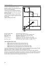
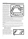
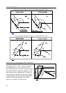
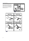
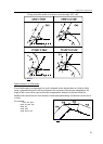
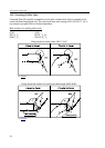
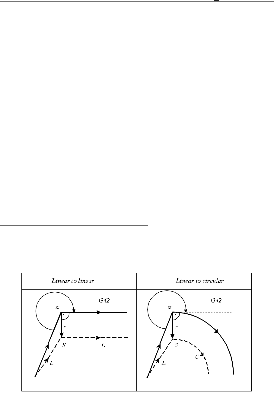
The basic instances of starting compensation up depending on the angle of " at the corner of the two
consecutive blocks and the type of interpolations (linear-to-linear, linear-to-circular) as shown
below. The Figures refer to instance G42, positive radius compensation assumed.
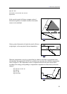
L Note: The symbols in the Figures (below and afterwards) have the following meanings:
r: value of radius compensation,
L: straight line
C: circular arc,
S: single block stop point,
Dashed line: the path of tool center,
Continuos line: the programmed path.
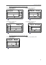
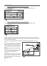
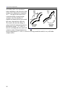
Basic instances of starting up the cutter compensation:
(G40) (G40)
G42 G01 X_ Y_ D_ G42 G01 X_ Y_ D_
X_ Y_ G2 X_ Y_ R_
Going around an inside corner, 180°<"<360°