


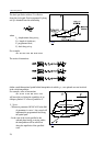

4.7 Cylindrical Interpolation (G7.1)
36
Fig. 4.7-2
2865
1
180
05. .
mm mm
⋅
°
°
⋅ =
π
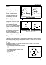
Application of tool radius compensation in case of cylindrical interpolation
Commands G41, G42 can be used in the usual manner in the switched-on state of cylindrical
interpolation. Though the following restrictions are in effect regarding its application:
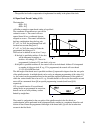
– Switch-on of cylindrical interpolation (command G7.1 Qr) is only possible in state G40.
– Should G41 or G42 be switched on in cylindrical interpolation mode, G40 must be programmed
before switching cylindrical interpolation off (command G7.1 Q0).
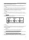
Programming restrictions in the course of cylindrical interpolation
The following commands are not available in the switched-on state of cylindrical interpolation:
– plane selection: G17, G18, G19,
– coordinate transformations: G52, G92,
– work coordinate system change: G54, ..., G59,
– positioning in machine coordinate system: G53,
– circular interpolation by giving circle center (I, J, K),
– drilling cycles.
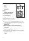
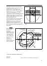
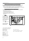
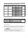
Example
The diagram beside shows a
path milled 3 mm deep on
the mantle of an R=28.65-
mm-radial cylinder. Rotating
tool T606 is parallel to the
axis X.. 1° movement on the
cylinder mantle is:
The axis order seen on the
diagram corresponds to
plane selection G19.
%O7602(CYLINDRICAL INTERPOLATION)
...
N020 G0 X200 Z20 S500 M3 T606
N030 G19 Z-20 C0 (G19: select plane C–Z)
N040 G1 X51.3 F100
N050 G7.1 C28.65 (cylindrical interpolation on, rotary
axis: C, cylinder radius: 28.65mm)
N060 G1 G42 Z-10 F250
N070 C30
N080 G2 Z-40 C90 R30
N090 G1 Z-60
N100 G3 Z-75 C120 R15
N110 G1 C180
N120 G3 Z-57.5 C240 R35
N130 G1 Z-27.5 C275