


PAGE 18 — FCG16HA SAW • OPERATION AND PARTS MANUAL — REV. #1 (03/19/10)
GUARDS, COVERS AND V-BELTS
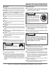
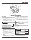
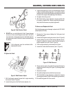
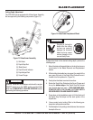
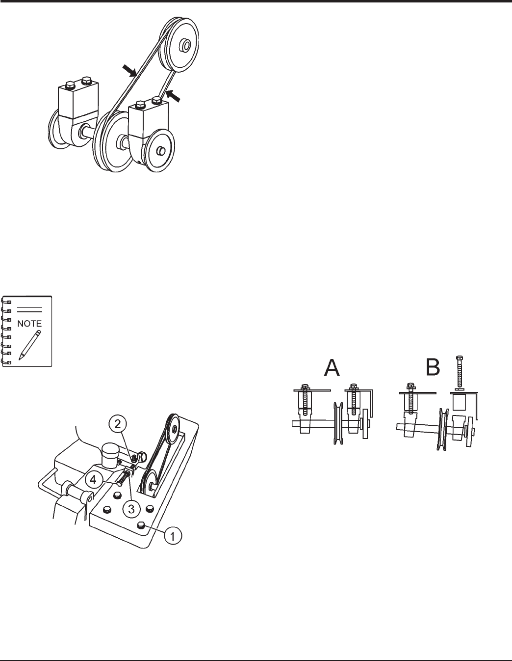
Figure 8. V-Belt Tension Check
4. DO NOT over or under tighten the V-belt. Severe damage
can occur to the saw and engine crank shaft if the belt is
over-tensioned. A decrease of power to the blade and poor
performance will result if the belt is under-tensioned (loose
on pulleys).
If the V-belt become worn or damaged, replace it with P/N 16052
(Gates/Optibelt 3VX335).
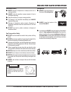
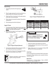
3. Tighten the adjusting hex screw (4) while holding the engine
in place to maintain pulley alignment. (a screwdriver can be
used as a lever at the rear belt guard mounting boss to hold
the back of the engine while adjusting V-belt tension.)
4. Re-tighten the locking nut (3).
5. With V-belt held in proper alignment, (engine parallel with
the frame), re-tighten the 4 engine mounting hex screws.
Verify that all hex screws are properly tightened.
To Tighten the V-belt:
V-belt alignment must be rechecked after
adjusting belt tension.
To Remove and Replace the V-belt:
1. Remove the 3 hex screws holding the V-belt guard and
remove the guard.
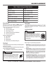
2. Loosen the 4 engine mounting hex screws. (item 2, Figure 9)
3. Loosen locking nut on the V-belt tension adjuster (item 3,
Figure 9). Loosen the tension on the V-belt by turning the
tension adjuster hex screw (item 4, Figure 9).
4. Pull the engine ahead to provide slack in the V-belt.
5. Loosen the 4 arbor shaft hex screws, (item 1, Figure 9).
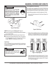
Figure 9. V-Belt Tension Adjust
1. With V-belt guard removed, loosen the 4 engine mounting
hex screws. (items 2 Figure 9)
2. Loosen locking nut on the V-belt tension adjuster, (3 ).
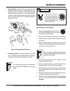
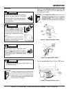
6. Remove the two outer arbor shaft hex screws allowing the
outside of the shaft to drop, (B in Figure 10), allowing removal
of the V-belt.
7. Reinstall new V-belt.
8. Re-install and tighten arbor shaft hex head screws.
9. With V-belt held in proper alignment, re-tighten the 4 engine
mounting hex screws. (Follow V-belt tightening procedures.)
10. Re-install belt guard with 3 hex screws.
Figure 10. V-Belt Removal