


125
CHAPTER 6 COMMUNICATIONS AMONG CPU MODULES
6
6.1 Communications Using the CPU Shared Memory
6.1.1 Communications by auto refresh (using the auto refresh area)
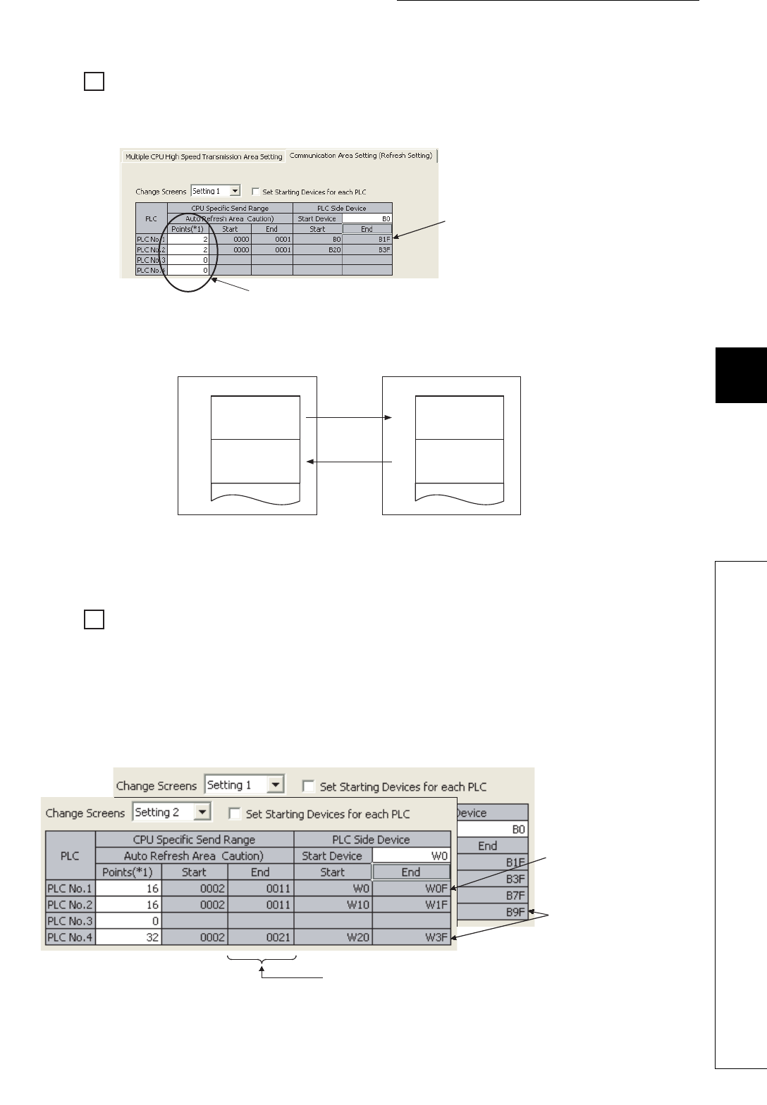
Ex.
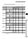
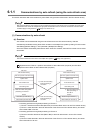
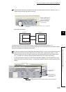
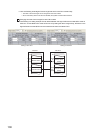
To refresh data in B0 to B1F (32 points) of CPU No.1 and B20 to B3F (32 points) of CPU No.2, set "2" in
"Points" because the link relay (B) is a bit device.
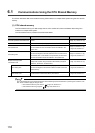
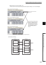
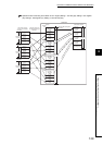
[Auto refresh processing]
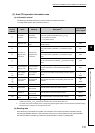
The auto refresh area in the CPU shared memory occupies a total points set for Setting 1 to 4.
When the number of send points is set, the corresponding start and end addresses of the auto refresh area are
automatically displayed in hexadecimal offset values.
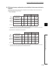
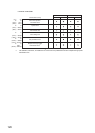
Ex.
For the CPU module having two auto refresh area settings (Setting 1 and 2), the end address of the auto
refresh area will be the one "start address of the auto refresh area + offset value of Setting 2". In the
following example, CPU No.1 and No.2 use the area from the start address of the auto refresh area to
0011
H
, and CPU No.4 uses the area from the start address of the auto refresh area to 0021
H
.
For the CPU module having only one auto refresh area setting (Setting 1), the end address of the auto
refresh area will be the one set in Setting 1. In the following example, CPU No.3 uses only the area set in
Setting 1.
Since the number of points for CPU No.3 and No.4 is set to "0", data are
not refreshed.
When the number of points in
the CPU shared memory is
set to "2" and a bit device is
specified for "PLC Side
Device", 32 points of data
can be refreshed.
CPU No.1
Device
B0
B1F
B20
B3F
Device
B0
B1F
B20
to
to
to
to
B3F
CPU No.2
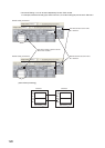
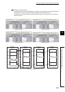
End addresses of the CPU shared memory in each CPU module
End addresses of
the devices in each
CPU module
Send range of
CPU No.1