


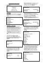

Select fluid type now appears on the
display. Use the scroll keys to select the
fluid type and press ENTER.
If the liquid you are measuring is not listed
select Other and enter a liquid sound
speed in metres/second. The sound speed
information can be found in the back of the
manual under Liquid Sound Speeds.
QUICK START
5
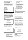
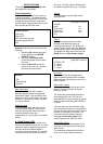
Select fluid type:
Water
Glycol/water 50/50
Lubricating oil
Diesel oil
Freon
Other (m/sec)
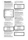
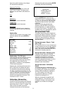
The instrument will now display the screen
below and provide the user with details of
the mode of operation and the maximum
flow rate that can be achieved from the
information entered. At this stage use the
keypad to check maximum volumetric
flows. If the display reads double bounce
or treble bounce the unit has calculated a
larger separation distance, but the
transducers should still be set up in reflex
mode.
Attach sensor set
in REFLEX mode
Approx. max. flow:
X.XX m/s
ENTER to continue
SCROLL changes mode
Select ENTER and the display will now
ask you to enter a temperature.
Enter the application temperature and
press ENTER. The display will now
display a sensor separation distance.
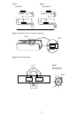
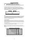
Follow the steps below to attach the guide
rail and transducers to the pipe.
1. Take the guide rail and apply
grease to the sensors as shown
on page 3 fig 2.
2. Turn thumbscrews on the top of
the guide rail clockwise to retract
the sensors back up into the guide
rail. This will keep the grease
away from the pipe until the guide
rail is attached.
3. Now strap the guide rail to the
pipe.
4. Screw down the fixed transducer
and slide the moveable transducer
to the required separation
distance (front edge of block), and
screw down on to the pipe.
5. Connect the RED and BLUE
sensor cables, between the guide
rail and the electronics.
6. Press ENTER to read flow.
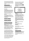
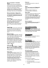
The flow reading now appears on the
display.
Batt CHRG
Sig 48%
(ERROR MESSAGES APPEAR HERE)
m/s
When reading volumetric flow the
instrument will display a positive and
negative total. Selecting OPTIONS from
the keypad can reset these totals (See
page 8).
The instrument will continually display the
battery and signal levels. Signal levels
should be above 30%, to obtain an
accurate reading.
If there is an error with the site data
entered or the application, the instrument
will display an Error or warning message
(See page 10), which will appear above
the flow reading. If there is more than one
message it will continually scroll between
them.
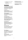
To stop reading flow, press ENTER
ONCE. The display will read the following.
This will stop all
Set sensor
Separation to
outputs
XXX
Press ENTER to EXIT
ENTER to continue
SCROLL to return
to READ FLOW
Pressing ENTER a second time will stop
outputs and return the instrument to the
MAIN MENU.
Press the scroll key to return the
instrument to READ FLOW.