


2
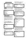
TRANSDUCER MOUNTING
1. OPERATION COMMENT
1.1 Remove oxidization, bitumen
or rubber from pipe surface
where the transducer
assembly is to be mounted.
Very thick asbestos, concrete, old
porous cast iron tubes and steel
pipes with scaled or badly corroded
internal surfaces can weaken the
signal and prevent the unit from
operating correctly.
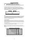
Mounting transducer assembly.
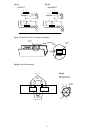
1.2 Turn the two knurled lock nuts
on the rail assembly (figure
3a), CLOCKWISE to withdraw
the transducers into the guide
rail and then apply ultrasonic
couplant as shown in figure 2,
page 3.
Straight pipe lengths either side of
the flow sensors should be 20
diameters UPSTREAM and 10
diameters DOWNSTREAM.
See figures 1a and 1b, page 3.
1.3 Position transducer assembly
onto prepared section of pipe
as recommended at 1.1. The
fixed transducer (Blue) should
be DOWNSTREAM from the
floating transducer (Red).
Strap to pipe securely using
the ball chain attached to the
rail.
The guide rail assembly must be in
alignment with the pipe axis and
positioned as shown in figure 3b
when attached to a horizontal pipe.
If the sensor cables are connected
in reverse the instrument will
display a negative flow rate, but this
will not affect the accuracy of the
reading.
1.4 Turn the knurled lock nut for
the fixed transducer ANTI-
CLOCKWISE to contact pipe
surface.
Do not over tighten. Do not lock
the floating transducer until the
‘separation distance’ has been
determined after programming the
unit.
1.5 Connect transducer assembly
to the handset with the cables
provided.
The Portaflow is now ready to
program.