SECTION 9—MOTOR LOCKS/FORKS
TDX™ Wheelchairs 66 Part No 1143150
NOTE: Motor package is designed for an occupant weight up to 400 lbs. Force to disengage motor
lock may exceed ANSI/RESNA wc/vol2-1998 requirements for section 14.7 paragraph 7.2d. The
RESNA requirements assume a maximum occupant weight of 220 lbs.
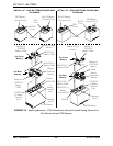
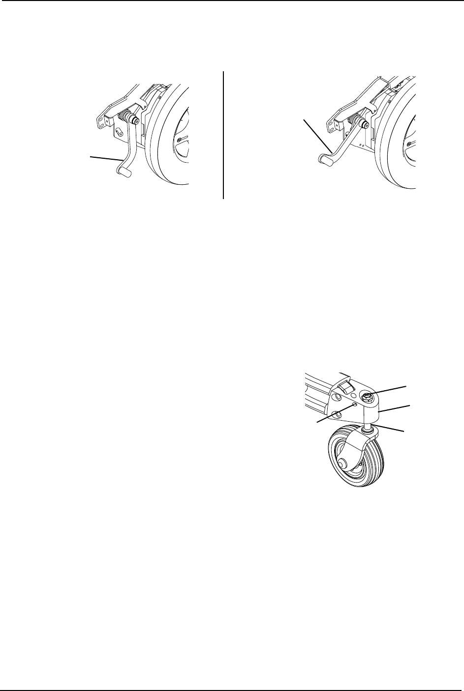
FIGURE 9.2 Disengaging/Engaging Motor Lock Levers - Gearless Brushless GB™Motors
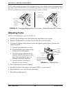
Adjusting Forks
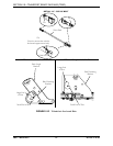
NOTE: For this procedure, refer to FIGURE 9.3.
1. Remove the retaining screw that secures the headtube cover in place.
2. Remove the headtube cover (not shown) from the caster headtube.
3. To properly tighten caster journal system and guard against flutter, perform the
following check:
A. Tip back the wheelchair to floor.
B. Pivot both forks and casters to top
of their arc simultaneously.
C. Let casters drop to bottom of arc
(wheels should swing once to one-
side, then immediately rest in a
straight downward position).
D. Adjust locknuts according to
freedom of caster swing.
FIGURE 9.3 Adjusting Forks
4. Test wheelchair for maneuverability.
5. Readjust locknuts if necessary, and repeat STEPS 1-3 until correct.
6. Snap headtube cover into the caster headtube.
7. Reinstall retaining screws.
Motor Lock
Lever
ENGAGE
(Drive
position)
Motor Lock
Lever
DISENGAGE
(Pull upward)
Locknut
Fork
Retaining
Screw
Caster
Headtube
NOTE: Headtube
cover not shown for
clarity.


