


6
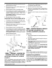
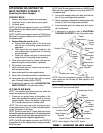
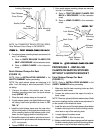
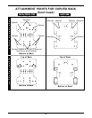
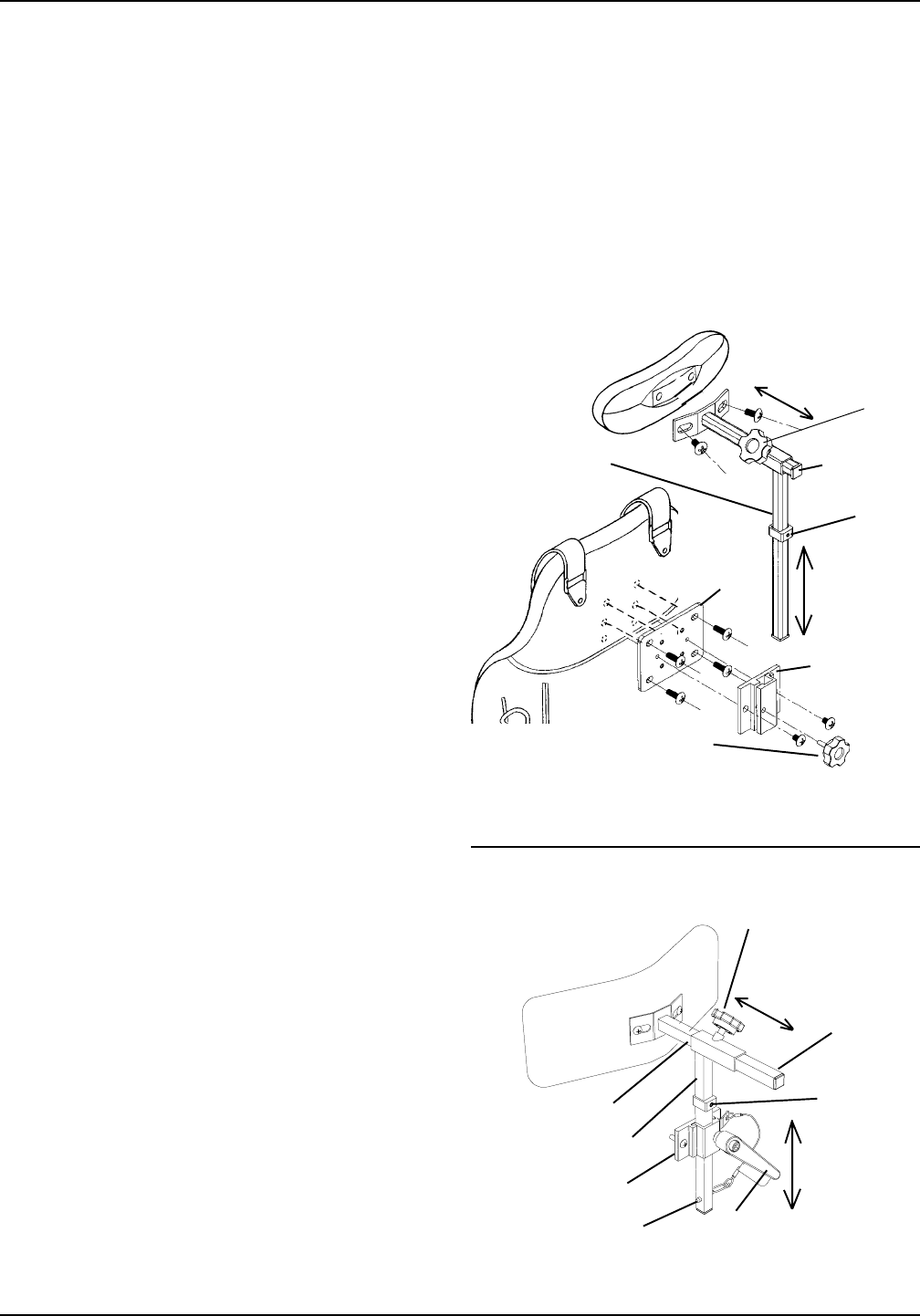
FIGURE 7 - FIGURE 7 -
FIGURE 7 - FIGURE 7 -
FIGURE 7 -
ADJUSTING ADJUSTING
ADJUSTING ADJUSTING
ADJUSTING
THE NECK SUPPORTHE NECK SUPPOR
THE NECK SUPPORTHE NECK SUPPOR
THE NECK SUPPOR
TT
TT
T
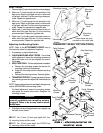
NOTE: Only the curved back is shown for clarity. The
neck support on the Ulti-mate Air Back adjusts in the
same manner.
Neck Support
Bracket
Thumbscrew Knob
Thumb-
screw
Knob
Height
Adjustment
Stop
Vertical Post
NOTE: If a NEW neck support is used on a NEW Curved
Back than the support bracket can be used WITHOUT
the adapter plate.
2. Secure neck adapter plate to the back shell with the
four (4) long mounting screws provided.
3. Attach neck support bracket to the adapter plate using
the two (2) short mounting screws provided.
4. Insert horizontal post into vertical post and secure
with thumbscrew.
5. If adjustment is required, refer to ADJUSTING
THE NECK SUPPORT in this instruction sheet.
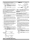
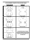
ATTACHING/ADJUSTING THE
NECK SUPPORT (FIGURE 7)
Attaching the Neck Support
CURVED BACK.
1. Remove neck support bracket from packaging.
2. Unzip back cover on both sides of center panel.
3. Lift center panel.
NOTE: If a NEW neck support is used on an EXISTING
Curved Back than the adapter plate and support bracket
MUST be used.
NOTE: If a NEW neck support is used on a NEW Curved
Back than the support bracket can be used WITHOUT
the adapter plate.
4. Perform Steps 4a. and 4b. or 4c.:
a. Secure neck adapter plate to the back shell
with the four (4) mounting screws provided (If
applicable).
b. Then secure the neck support bracket to the
neck adapter plate using the two (2) mounting
screws provided.
c. Secure the vertical neck post to the back shell
using the two (2) mounting screws provided.
5. Close center panel with the vertical neck post ex-
posed through the slot provided in upholstery.
6. Zip the back cover closed.
7. Insert horizontal post into vertical post and secure
with thumbscrew knob.
8. Insert vertical post into neck support bracket.
9. Secure with a thumbscrew knob or adjustable lever.
10. Insert detent pin into through both walls of vertical
post (Transport Ready Option [TRRO]).
11. If adjustment is required, refer to ADJUSTING THE
NECK SUPPORT in this instruction sheet.
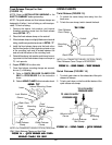
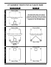
ULTI-MATE AIR BACK.
NOTE: The standard attachment points are where the
eyelets are located in the upholstery.
1. If there are no eyelets, pierce a hole pattern in the
fabric, that resembles the pattern found on the neck
support bracket. Ensure the pattern is aligned with
the T-nutted holes found on the back shell.
NOTE: The cover may need to be removed to get a
more precise location of the T-nutted holes before pierc-
ing the hole pattern in the fabric.
NOTE: There is an extra set of T-nutted holes found on the
back shell for optional height adjustment. To make these holes
accessible, pierce a hole in the fabric aligned with the T-nut-
ted hole in the back shell. Repeat for opposite hole.
NOTE: If a NEW neck support is used on an EXISTING
Curved Back than the adapter plate and support bracket
MUST be used.
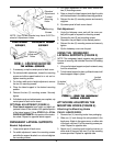
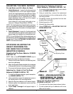
Neck
Adapter
Plate
Depth
Adjustment
Horizontal
Post
Height
Adjustment
Thumbscrew Knob
Neck Support
Bracket
Height
Adjustment
Stop
Vertical Post
NOTE: Neck Adapter Plate NOT shown.
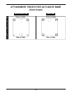
Horizontal Post
Adjustment Lever
Detent Pin
Height
Adjustment
Depth
Adjustment
NOTE: Ensure that the retaining screw is located
in the end of the horizontal post.
Retaining
Screw