


2
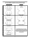
NOTE: On the back, the standard attachment points are
the top and bottom sets of holes. Refer to the ATTACH-
MENT POINTS chart in this instruction sheet for optional
attachment points.
4. Install four (4) of the mounting screws through the
holes in the growth bracket and into the underside of
the Ulti-Mate Base. Securely tighten.
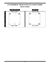
NOTE: On the seat, the standard attachment points are
the front and back sets of holes. Refer to the ATTACH-
MENT POINTS chart in this instruction sheet for optional
attachment points.
5. If adjustment is required, refer to ADJUSTING THE
GROWTH BRACKET in this instruction sheet. Oth-
erwise, continue on with ATTACHING/ADJUSTING
THE LATERAL SUPPORTS in this instruction sheet.
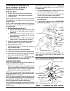
ADJUSTING THE ULTI-MATE BASE
DEPTH.
1. Remove the four (4) mounting screws that secure
the growth bracket to the Ulti-Mate Base.
2. Adjust the seat forward or back until the desired
mounting position is obtained.
3. Reinstall the four (4) mounting screws through the
growth bracket and into the seat. Securely tighten.
Refer to the ATTACHMENT POINTS
chart
in this
instruction sheet for standard and optional attach-
ment points.
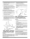
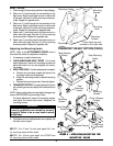
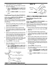
ATTACHING / ADJUSTING THE
ADJUSTABLE ANGLE GROWTH
BRACKET (FIGURE 2)
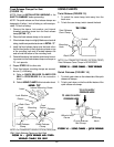
ATTACHING THE ADJUSTABLE ANGLE
GROWTH BRACKET
NOTE: The growth bracket attaches to the child/junior
sized curved back ONLY.
1. Remove the adjustable angle growth bracket and
attaching hardware from the packaging.
2. Unzip the center panel of the back cover, exposing
the six (6) T-nutted mounting holes.
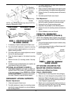
NOTE: Make sure that the growth bracket is positioned
correctly. The flat portion of the adjustable angle bracket
growth bracket provides depth adjustment for the Ulti-
mate base. The angled portion of the adjustable angle
bracket height adjustment for the curved back
(FIGURE 1).
3. Install four (4) of the mounting screws through the
slots in the adjustable angle growth bracket and into
the underside of the Ulti-mate base. Securely tighten.
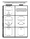
NOTE: On the Ulti-mate base, the standard attachment
points are the front and rear four (4) holes. Refer to the
ATTACHMENT POINTS
in this instruction sheet for
optional attachment points.
4. Install two (2) of the mounting screws through the
slots on the adjustable angle growth bracket and
into the back shell. Securely tighten.
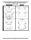
NOTE: On the curved back, the standard attachment
points are the MIDDLE set of holes. Refer to the
ATTACHMENT POINTS
in this instruction sheet for
optional attachment points.
5. If adjustment is required, refer to ADJUSTING THE
GROWTH BRACKET in this instruction sheet.
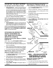
ADJUSTING THE GROWTH BRACKET
ADJUSTING THE BACK HEIGHT.
1. If necessary, unzip center panel of the back cover.
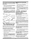
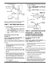
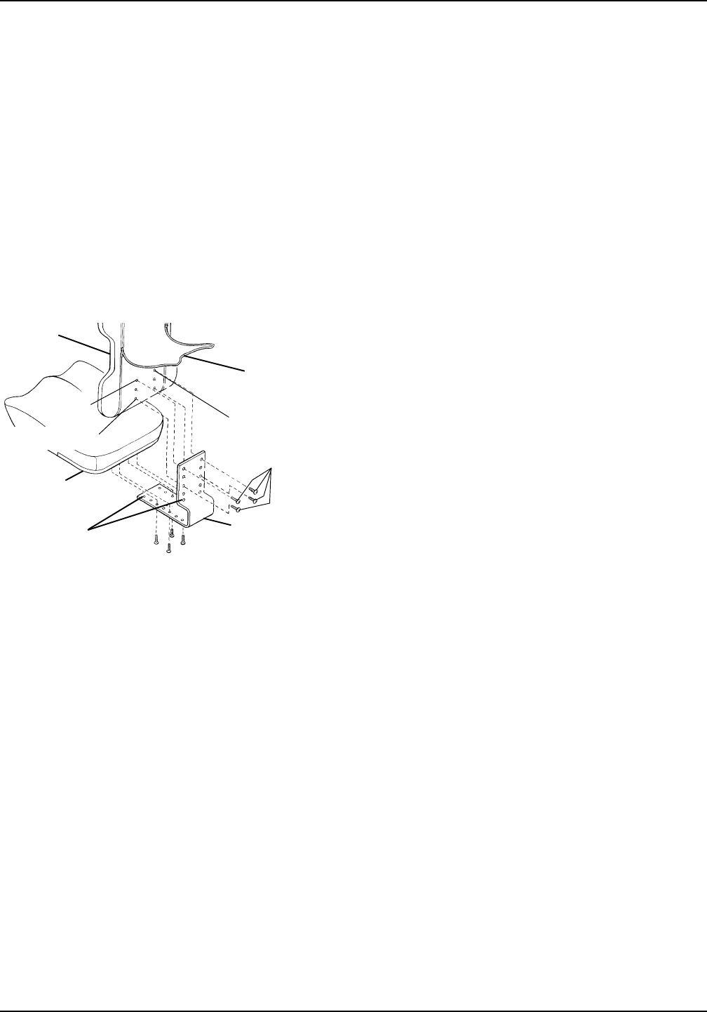
Adjusting the Growth Bracket (FIGURE 1)
NOTE:The growth bracket provides up to a 3-inch depth
adjustment and up to a 3-inch height adjustment.
ADJUSTING THE BACK HEIGHT.
1. If necessary, unzip center panel of the back cover.
2. Remove the four (4) mounting screws that secure
the growth bracket to the back.
3. Adjust the back up or down until the desired mount-
ing position is obtained.
4. Reinstall the four (4) mounting screws through the
growth bracket and into the back shell. Securely
tighten. Refer to the ATTACHMENT POINTS
chart
in this instruction sheet for standard and optional
attachment points.
5. If all attachments and adjustments are complete, zip
center panel of back cover closed.
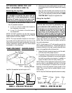
Bottom Set
Growth Bracket
Adjustment
Holes
Ulti-Mate
Base
Six (6) T-nutted
Mounting Holes
Center Panel
Curved
Back
Mounting
Screws
FIGURE 1 - FIGURE 1 -
FIGURE 1 - FIGURE 1 -
FIGURE 1 -
AA
AA
A
TTTT
TTTT
TT
AA
AA
A
CHING/ADJUSTING CHING/ADJUSTING
CHING/ADJUSTING CHING/ADJUSTING
CHING/ADJUSTING
THE FIXEDTHE FIXED
THE FIXEDTHE FIXED
THE FIXED
GRGR
GRGR
GR
OO
OO
O
WTH BRAWTH BRA
WTH BRAWTH BRA
WTH BRA
CKETCKET
CKETCKET
CKET
-CHILD/JUNIOR SIZES-CHILD/JUNIOR SIZES
-CHILD/JUNIOR SIZES-CHILD/JUNIOR SIZES
-CHILD/JUNIOR SIZES
NOTE: Your Growth Bracket may have SLOTS in-
stead of Adjustment Holes.
Top Set