


4
Slot
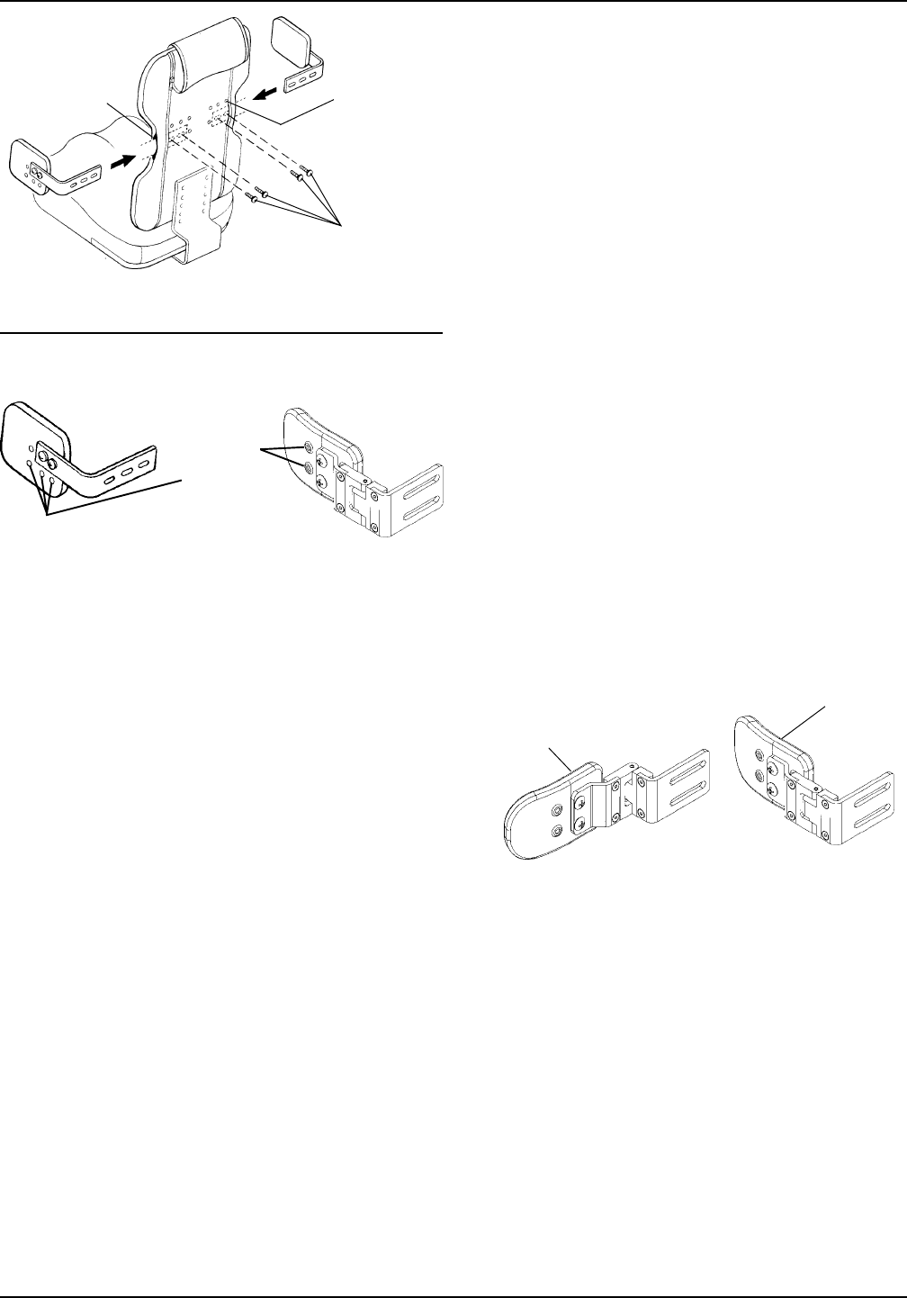
Optional
Adjustment
Holes
FIGURE 4 - FIGURE 4 -
FIGURE 4 - FIGURE 4 -
FIGURE 4 -
AA
AA
A
TTTT
TTTT
TT
AA
AA
A
CHING/ADJUSTINGCHING/ADJUSTING
CHING/ADJUSTINGCHING/ADJUSTING
CHING/ADJUSTING
THE LATHE LA
THE LATHE LA
THE LA
TERAL SUPPORTERAL SUPPOR
TERAL SUPPORTERAL SUPPOR
TERAL SUPPOR
TSTS
TSTS
TS
Standard
Adjustment
T-nutted
Mounting
Holes
Mounting
Screws
FIXED LAFIXED LA
FIXED LAFIXED LA
FIXED LA
TERALTERAL
TERALTERAL
TERAL
SUPPORSUPPOR
SUPPORSUPPOR
SUPPOR
TT
TT
T
SWINGASWINGA
SWINGASWINGA
SWINGA
WW
WW
W
AA
AA
A
Y LAY LA
Y LAY LA
Y LA
TERALTERAL
TERALTERAL
TERAL
SUPPORSUPPOR
SUPPORSUPPOR
SUPPOR
TT
TT
T
Locked
Position
Unlocked
Position
FIGURE 5 - USING FIGURE 5 - USING
FIGURE 5 - USING FIGURE 5 - USING
FIGURE 5 - USING
THE SWINGATHE SWINGA
THE SWINGATHE SWINGA
THE SWINGA
WW
WW
W
AA
AA
A
YY
YY
Y
LALA
LALA
LA
TERAL SUPPORTERAL SUPPOR
TERAL SUPPORTERAL SUPPOR
TERAL SUPPOR
TSTS
TSTS
TS
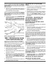
1. If necessary, unzip the center panel of back cover.
2. For minimal width adjustment, loosen the mounting
screws and slide support bracket in or out and re-
tighten mounting screws.
3. For further width and/or height adjustment, remove
the two (2) mounting screws.
4. Place the lateral support in the desired mounting
position.
5. Reinsert the two (2) mounting screws. Securely
tighten.
6. If all attachments and adjustments are complete, zip
center panel of back cover closed.
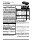
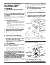
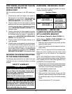
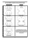
OPTIONAL ADJUSTMENT (FIGURE 4).
1. Fixed lateral supports have height and depth ad-
justment holes on the outside of the padded portion
of the lateral support. Follow STEPS 3-5 in STAN-
DARD ADJUSTMENTS in this section of the instruc-
tion sheet. Repeat for opposite lateral support.
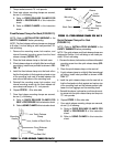
SWINGAWAY LATERAL SUPPORTS
Bracket Adjustment
1. Unzip center panel of back cover.
2. For width adjustment, loosen the mounting screws
and slide the support bracket in or out and retighten
the mounting screws.
3. For height adjustment on adult sizes, remove the
two (2) mounting screws.
4. Raise or lower the lateral support and align the slots
with the back holes in the desired mounting positions.
5. Reinsert the two (2) mounting screws and securely
retighten.
6. Zip center panel of back cover closed.
Pad Adjustment
1. Unzip the hideaway cover and pull the cover par-
tially off the pad to expose the mounting screws.
2. Remove the two (2) pad mounting screws.
3. Reposition the pad depth to the desired position.
4. Reinsert the two (2) mounting screws and securely
tighten.
5. Zip the hideaway cover over the pad.
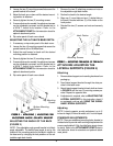
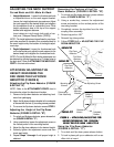
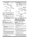
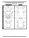
USING THE SWINGAWAY
LATERAL SUPPORTS (FIGURE 5)
NOTE: The swingaway lateral supports were designed
for ease in removing the individual from the KSS seating
system.
1. Lift up on the lateral support and push outward, away
from the wheelchair.
2. To lock lateral support in place, pull back inward until
lateral support snaps in place.
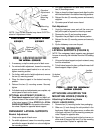
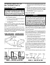
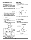
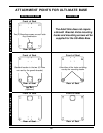
NOTE: Your Growth Bracket may have SLOTS in-
stead of Adjustment Holes.
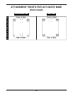
ATTACHING/ADJUSTING THE
MOUNTING HOOKS (FIGURE 6)
Attaching the Mounting Hooks
CHILD/JUNIOR SIZES.
1. Remove four (4) mounting hooks from packaging.
2. Slide one (1) hook through the slot provided in the
back cover. Attach to the upper corner, on either side
of the back, with two (2) of the mounting screws pro-
vided. Repeat for opposite side.
3. Attach one (1) mounting hook to the front corner, on
either side of the seat, with two (2) of the mounting
screws provided. Repeat for opposite side.