


3
2. Loosen the two (2) mounting screws that secure the
growth bracket to the back.
3. Adjust the back up or down until the desired mount-
ing position is obtained.
4. Securely tighten the two (2) mounting screws.
5. If more adjustment is needed, the adjustment screws
can be completely removed, and the bracket set to
a NEW T-nutted hole location. Refer to the
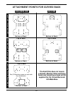
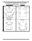
ATTACHMENT POINTS
in this instruction sheet for
optional attachment points.
6. Zip center panel of back cover closed.
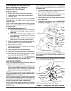
ADJUSTING THE ULTI-MATE BASE DEPTH.
1. If necessary, unzip center panel of the back cover.
2. Loosen the four (4) mounting screws that secure the
growth bracket to the Ulti-Mate Base.
3. Adjust the seat forward or back until the desired
mounting position is obtained.
4. Securely tighten the two (2) mounting screws.
5. If more adjustment is needed, the adjustment screws
can be completely removed, and the bracket set to
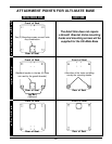
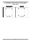
a NEW T-nutted hole location. Refer to the
ATTACHMENT POINTS
in this instruction sheet for
optional attachment points.
6. Zip center panel of back cover closed.
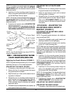
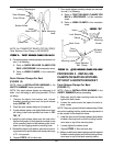
Bottom Mounting
Screws
Top Mounting
Screws
FIGURE 2 - FIGURE 2 -
FIGURE 2 - FIGURE 2 -
FIGURE 2 -
AA
AA
A
TTTT
TTTT
TT
AA
AA
A
CHING / CHING /
CHING / CHING /
CHING /
ADJUSTING ADJUSTING
ADJUSTING ADJUSTING
ADJUSTING
THETHE
THETHE
THE
ADJUSTADJUST
ADJUSTADJUST
ADJUST
ABLE ABLE
ABLE ABLE
ABLE
ANGLE GRANGLE GR
ANGLE GRANGLE GR
ANGLE GR
OO
OO
O
WTH BRAWTH BRA
WTH BRAWTH BRA
WTH BRA
CKETCKET
CKETCKET
CKET
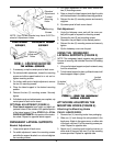
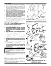
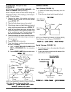
ATTACHING/ADJUSTING THE
LATERAL SUPPORTS (FIGURE 4)
Attaching
1. Remove lateral support and mounting hardware from
packaging.
2. Feed lateral support bracket through the slots pro-
vided in the back cover.
3. Attach lateral support bracket to back shell as shown
in FIGURE 2 with the two (2) mounting screws pro-
vided. Repeat for opposite side.
4. If adjustment is required, refer to ADJUSTING THE
LATERAL SUPPORTS in this instruction sheet. If
so equipped continue with USING THE SWING-
AWAY LATERAL SUPPORTS.
Adjusting
NOTE: Lateral supports provide adjustment up to 2-
inches for height; 2-inches for width, and 1-inch for depth.
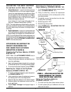
STANDARD ADJUSTMENTS.
NOTE: There are additional mounting holes located on
the back shell to provide width and height adjustment for
a more comfortable fit. Only the child/junior size is shown
for clarity. Refer to the ATTACHMENT POINTS chart in
this instruction sheet for standard and optional attach-
ment points.
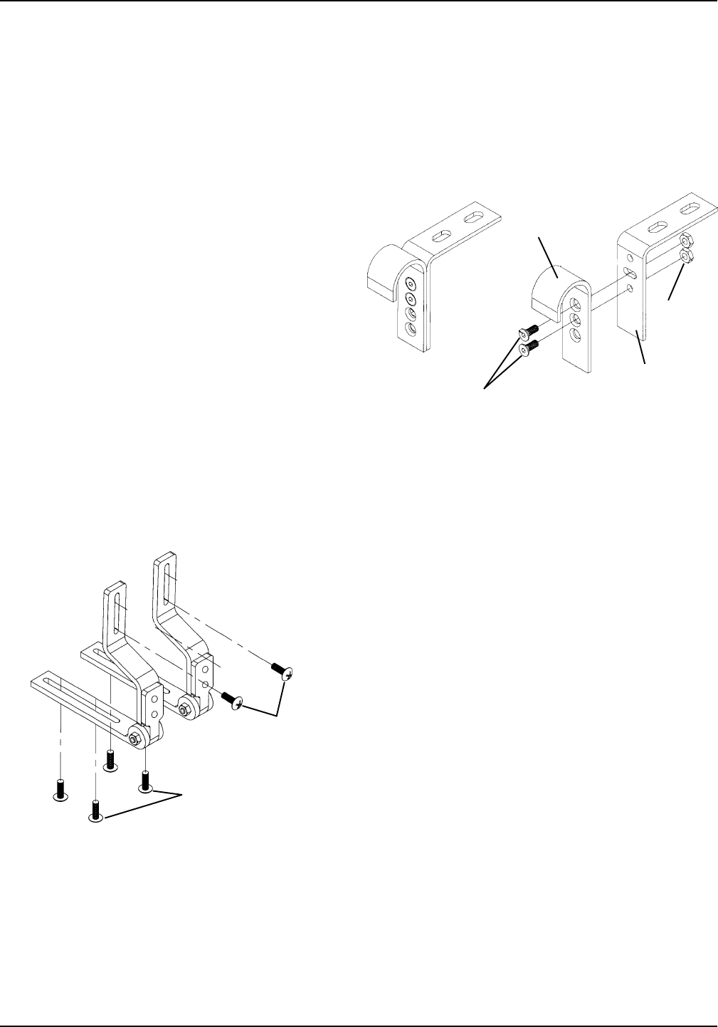
1. Remove the two (2) attaching screws and nuts on
the adjustable angle back hooks.
2. Recline the back to the desired angle.
3. Align one (1) round hole and one (1) slotted hole on
the back L-bracket with two (2) of the holes on the
hook portion.
4. Reinstall the two (2) screws and nuts and securely
tighten.
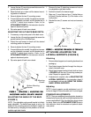
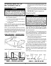
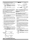
FIGURE 3 - FIGURE 3 -
FIGURE 3 - FIGURE 3 -
FIGURE 3 -
ADJUSTING ADJUSTING
ADJUSTING ADJUSTING
ADJUSTING
THE THE
THE THE
THE
ANGLE OF ANGLE OF
ANGLE OF ANGLE OF
ANGLE OF
THE BTHE B
THE BTHE B
THE B
AA
AA
A
CKCK
CKCK
CK
Attaching Screws
Nuts
L-Bracket
Hook Portion
ADJUSTING THE ANGLE OF THE BACK
(FIGURE 3)
NOTE: The adjustable angle growth bracket is infinitely
angle adjustable. The back-to-seat angle is set by the
location of the mounting points for the back in relation to
the base and by changing the hole positions of the ad-
justable angle back hooks.