


10
FIGURE 11- FIGURE 11-
FIGURE 11- FIGURE 11-
FIGURE 11-
TWIST RELEASE CLAMPS FOR BTWIST RELEASE CLAMPS FOR B
TWIST RELEASE CLAMPS FOR BTWIST RELEASE CLAMPS FOR B
TWIST RELEASE CLAMPS FOR B
AA
AA
A
CKCK
CKCK
CK
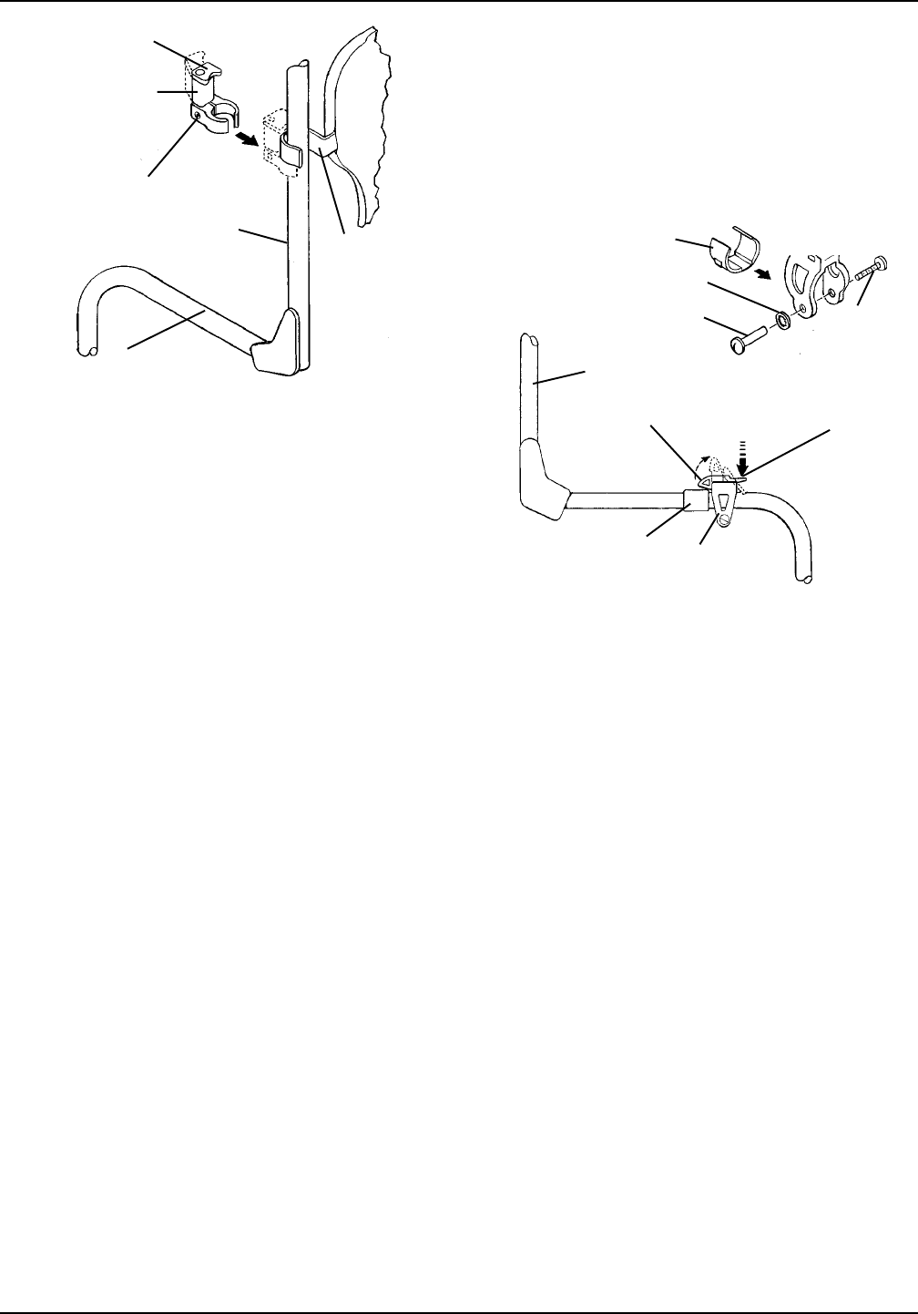
Twist Release
Cane Clamp
Inside
Back Cane
Seat Rail
Back Mounting
Hook
Socket Screw
Locking Mechanism
FIGURE 12- QUICK RELEASE CLAMPS FOR SEAFIGURE 12- QUICK RELEASE CLAMPS FOR SEA
FIGURE 12- QUICK RELEASE CLAMPS FOR SEAFIGURE 12- QUICK RELEASE CLAMPS FOR SEA
FIGURE 12- QUICK RELEASE CLAMPS FOR SEA
TT
TT
T
Lock Washer
Internal
Mounting
Screw
Quick Release
Rail Clamp
Mounting Hook
Back Cane
Fixed
Portion
Release
Portion
Insert
DETDET
DETDET
DET
AIL AIL
AIL AIL
AIL
““
““
“
A”A”
A”A”
A”
8. Once twist release mounting clamps are secured, do
one (1) of following:
A. Refer to QUICK RELEASE CLAMPS FOR
SEAT in PROCEDURE 1 of this instruction sheet.
B. Refer to USING CLAMPS in this instruction
sheet.
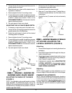
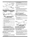
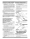
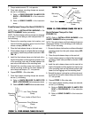
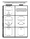
Quick Release Clamps For Seat
(FIGURE 12)
NOTE: Refer to INSTALLATION WARNING in the
SAFETY SUMMARY before proceeding.
NOTE: The quick release clamps are designed to fit
either 1-inch rail tubing or, with insert provided, 7/8-inch
rail tubing.
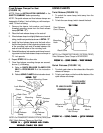
1. Remove the sleeve, lock washer, and internal
threaded mounting screw from the quick release
clamp (DETAIL “A”).
2. Place the quick release clamp on the seat rail.
3. If quick release clamp is not tightly fitted around seat
rail tubing, install insert provided as shown in DE-
TAIL “A”.
4. Install the quick release clamp onto the seat rail so
that the fixed portion is flush against and rests on top
of the mounting hook and the release portion is be-
tween the front riggings and the mounting hook.
5. Reinstall the sleeve, lock washer, and internal mount-
ing screw into the quick release rail clamp and torque
to 75 - inch pounds.
6. Repeat STEPS 1- 5 for other side.
7. Once quick release mounting clamps are secured,
do one (1) of following:
A. Refer to TWIST RELEASE CLAMPS FOR
BACK in PROCEDURE 1 of this instruction
sheet.
B. Refer to USING CLAMPS in this instruction
sheet.
PROCEDURE 2 - INSTALLING
CLAMPS ON SEATING SYSTEMS
WITHOUT A GROWTH BRACKET
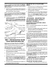
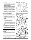
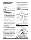
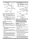
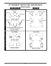
Twist Release Clamps For Back
(FIGURE 11)
NOTE: Refer to INSTALLATION WARNING in the
SAFETY SUMMARY before proceeding.
1. Make sure that the back mounting hooks are flush
against the back canes.
2. Loosen the socket screw that opens the twist re-
lease clamp.
NOTE: There is a right and left twist release clamp. Make
sure when installing that the socket screw adjustment is
on the outside of the wheelchair frame.
3. Install the open end of the twist release clamp below
the back mounting hook so that the locking mecha-
nism rests on top of the mounting hook.
4. Loosely tighten the socket screw.
5. Repeat STEPS 1- 4 for the other side.
6. Make sure both twist release clamps are flush against
the back mounting hooks and that the locking mecha-
nism rests on top of the back mounting hooks.
Sleeve
NOTE: For TRANSPORT READY OPTION (TRRO)
Twist Release Cane Clamp is REVERSED.