


10
INSTALLING/REMOVING THE
INFINITY LOBACK (FIGURE 1)
WARNING
After ANY adjustments, repair or service and
BEFORE use, make sure that all attaching hard-
ware is tightened securely - otherwise injury or
damage may result.
NOTE: Refer to the INSTALLATION AND STABILITY
WARNINGS in the SAFETY SUMMARY of this manual.
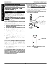
Installing the Infinity LoBack
1. Ensure the two (2) cane clamps are properly installed
onto the wheelchair frame. Refer to INSTALLING/
REMOVING CANE CLAMPS in PROCEDURE 1 of
this manual.
2. If necessary, adjust the Infinity LoBack to fit on the
back canes. Refer to
ADJUSTING THE INFINITY
LOBACK in PROCEDURE 4 of this manual.
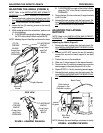
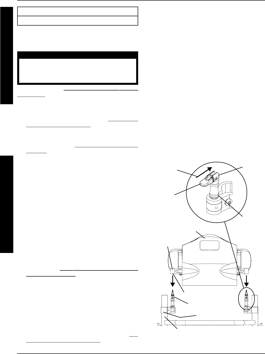
3. Align the mounting holes in the two (2) Infinity LoBack
mounting clamps with the locking pins on the two (2)
cane clamps (FIGURE 1).
4. Lower the Infinity LoBack onto the wheelchair back
canes, making sure the locking pins on the two (2)
cane clamps pass through the mounting holes in the
two (2) mounting clamps of the Infinity LoBack.
5. Firmly grasp the handle of the locking pin and bend it
DOWN until it forms a 90
o
angle with the rest of the
locking pin, then push it FORWARD to fully engage
the lock. (DETAIL “A”).
NOTE: The locking pin is fully engaged when the handle
of the locking pin bends down to form a 90° angle with the
rest of the of the locking pin.
6. Repeat STEP 5 for the opposite locking pin.
7. Ensure all cushions and lateral supports have been in-
stalled. Refer to
PREPARING THE INFINITY BACK
FOR INSTALLATION in PROCEDURE 2 of this
manual.
8. Position the user into the wheelchair to determine
which adjustments need to be made to properly fit
the Infinity LoBack. Refer to the wheelchair owner’s
manual.
9. Remove the user from the wheelchair. Refer to the
wheelchair owner’s manual.
10. Perform the following procedures to adjust the Infin-
ity LoBack to fit the user if necessary. Refer to
AD-
JUSTING THE INFINITY LOBACK in PROCEDURE
4 of this manual.
This Procedure includes the following:
Installing/Removing the Infinity LoBack
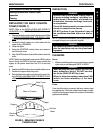
A. ADJUSTING THE MOUNTING HARDWARE/
HEIGHT
B. ADJUSTING THE DEPTH HARDWARE
C. ADJUSTING THE ANGLE
D. ADJUSTING THE LATERAL SUPPORTS
NOTE: Perform the above procedures in the order listed.
11. Inspect all mounting screws to ensure ALL hardware
has been tightened securely. Torque to 45-50 in./lbs.
13. If necessary, repeat STEPS 8-11 until the user is com-
fortable.
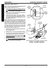
Removing the Infinity LoBack
1. Grasp the handle of one (1) of the locking pins and
push it BACK to release the lock, and then pull it UP-
WARD until the handle is parallel with the rest of the
locking pin.
2. Repeat STEP 5 for the opposite locking pin.
3. Grasp the Infinity Loback from the bottom and pull
upward to release it from the mounting pins on the
two (2) cane clamps.
4. Remove the Infinity LoBack.
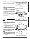
FIGURE 1 - INSTALLING/REMOVING THE INFINITY
LOBACK
PROCEDURE 3 INSTALLING/REMOVING THE INFINITY LOBACK
I
N
S
T
A
L
L
I
N
G
/
R
E
M
O
V
I
N
G
T
H
E
L
O
B
A
C
K
Locking Pin
Mounting
Clamp
Mounting Hole
Cane Clamp
Back Cane
Infinity LoBack
Locking
Pin
Locks to
Form A
90
o
Angle
DETAIL “A”
Pull Handle
Forward to
Engage Lock
Handle