


51
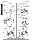
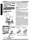
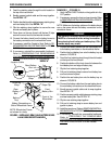
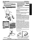
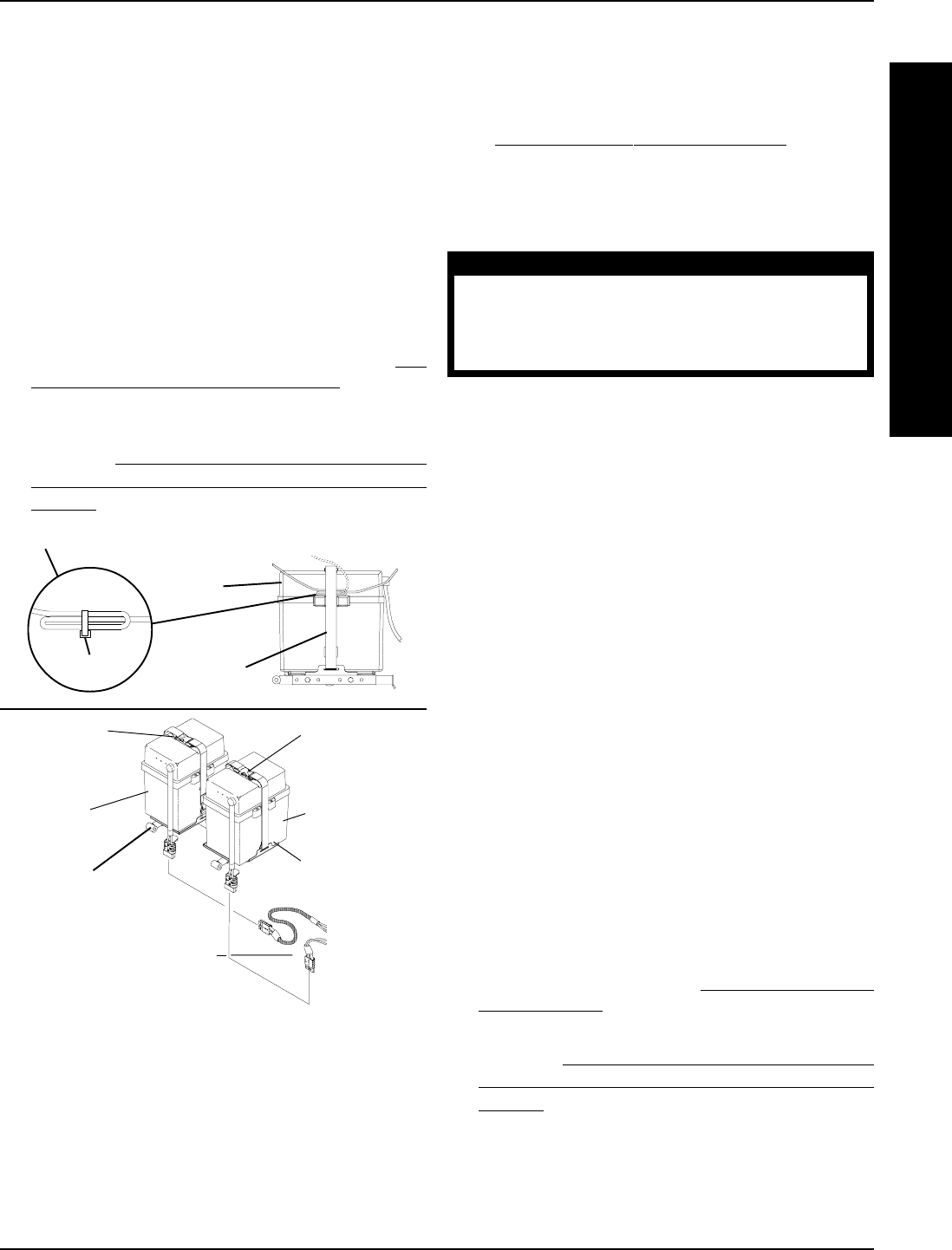
Retaining
Strap Clip
Battery Connections on
Side of Wheelchair Frame
Retaining
Strap
NOTE: Wheelchair Frame
not shown for clarity.
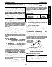
FIGURE 5 - INSTALLING/REMOVING BATTERY BOXES
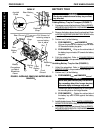
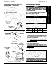
ALL MODELS EXCEPT RANGER II
JR
Front
Battery Box
Front of the
Wheelchair
Rear
Battery
Box
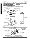
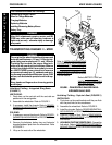
PROCEDURE 11FWD WHEELCHAIRS
F
W
D
W
H
E
E
L
C
H
A
I
R
S
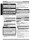
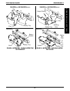
RANGER II
JR
(FIGURE 6).
1. Verify that the ON/OFF switch on the joystick is in the
OFF position.
2. If necessary, remove the front and rear shrouds. Refer
to
REMOVING/INSTALLING SHROUDS in PROCE-
DURE 9 of this manual.
NOTE: Make sure the battery cables on the battery boxes
are on the same side as the battery connectors on the
wheelchair frame.
WARNING
The battery connector on the front battery box
MUST be connected to the wiring harness be-
fore placing front battery on battery tray. Oth-
erwise, injury may result.
3. Connect the battery cables from the front battery box
to the battery connectors on the wheelchair frame.
4. Position the front battery box onto the battery tray as
shown in FIGURE 6.
5. Feed the front retaining strap through the slot located
on the top of the front shroud.
6. Position the bottom of the front shroud in-between the
front battery box and edge of battery tray.
7. Clip the front retaining strap together.
8. Pull end of retaining strap to secure front battery box
and front shroud in place.
9. Position the rear battery box onto the battery tray as
shown in FIGURE 6.
10. Connect the battery cable from the rear battery box to
the rear battery connectors on the wheelchair frame.
11. Bundle excess joystick cable and tie wrap together.
See DETAIL "A".
12. Position excess joystick cable between retaining strap
and rear battery box. See DETAIL "A".
13. Clip the rear retaining strap together.
14. Pull end of retaining strap to secure battery box and
joystick in place.
15. Install the rear shroud. Refer to
REMOVING/INSTALL-
ING SHROUDS in PROCEDURE 9 of this manual.
16. If necessary, reinstall the removeable footboard.
Refer to
PREPARING THE REMOVEABLE
FOOTBOARD FOR WHEELCHAIR TRANSPOR-
TATION in PROCEDURE 3 of this manual.
Battery
Tray
8. Feed the retaining strap through the slot located on
the top of the rear shroud.
9. Bundle excess joystick cable and tie wrap together.
See DETAIL "A".
10. Position bundled joystick cable between retaining strap
and rear battery box. See DETAIL "A".
11. Clip the retaining strap together to secure the rear
shroud and battery box in place.
12. Press down on the rear shroud until the two (2) clips
secure the rear shroud to the two side shrouds.
13. Connect the battery leads from the battery boxes to
the battery connectors on the wheelchair frame.
14. If necessary, install the Captain's Seat. Refer to
RE-
MOVING/INSTALLING CAPTAIN'S SEAT in PROCE-
DURE 5 of this manual.
15. If necessary, reinstall the removeable footboard.
Refer to
PREPARING THE REMOVEABLE
FOOTBOARD FOR WHEELCHAIR TRANSPOR-
TATION in PROCEDURE 3 of this manual.
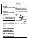
Joystick Cable
Tie-Wrap
Retaining
Strap
Rear Battery
Box
DETAIL "A"