32
E
L
E
C
T
R
O
N
I
C
S
PROCEDURE 6 ELECTRONICS
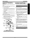
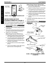
REPOSITIONING BATTERY
CHARGER CONNECTOR (FIGURE 4)
NOTE: The following procedure applies to FWD wheel-
chairs that are equipped with MKIV controllers ONLY.
1. Fold the wheelchair. Refer to TRANSPORTING
RANGER II FWD in PROCEDURE 11 of this manual.
2. If necessary, remove the battery charger cover from
the filler shroud.
3. Remove the hex bolt and locknut that secures the bat-
tery charger connector bracket to the wheelchair.
4. Perform one (1) of the following:
Battery Charger Connector Cable too Long -
A. Reposition the battery charger connector bracket
on the opposite side of the wheelchair frame.
B. Line up the mounting holes in the battery charger
connector bracket and the wheelchair frame.
C. Install the hex bolt through the wheelchair frame
and battery charger bracket.
D. Install the locknut onto the hex bolt and tighten
securely.
E. Tuck the excess battery charger cable into the
spiral wire cover on the wiring harness.
Battery Charger Connector Cable too Short -
A. Pull the battery charger cable out of the spiral
wire cover on the wiring harness.
B. Reposition the battery charger connector bracket
on the opposite side of the wheelchair frame.
C. Line up the mounting holes in the battery charger
connector bracket and the wheelchair frame.
D. Install the hex bolt through the wheelchair frame
and battery charger bracket.
E. Install the locknut onto the hex bolt and tighten
securely.
5. If necessary, install the battery charger cover on the
opposite filler shroud.
6. Unfold the wheelchair. Refer to
TRANSPORTING
RANGER II FWD in PROCEDURE 11 of this manual.
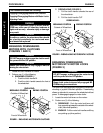
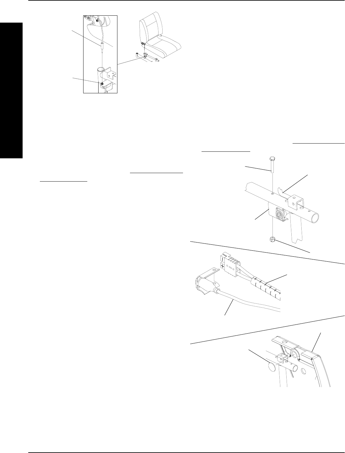
Hex Bolt
Locknut
Wheelchair
Frame
Battery Charger
Connector Bracket
FIGURE 4 - REPOSITIONING BATTERY CHARGER
CONNECTOR
Spiral Wire Cover
Battery Charger Cable
Battery Charger
Cover
Filler Shroud
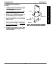
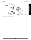
Limit Switch
Phono Plug
Limit Switch
Phono Jack
FIGURE 3 - DISCONNECTING/CONNECTING LIMIT
SWITCH


