


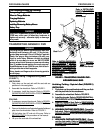

43
PROCEDURE 10BATTERIES
B
A
T
T
E
R
I
E
S
CONNECTING BATTERY CABLES
WARNING
NEVER allow any of your tools and/or battery
cable(s) to contact BOTH battery terminal(s)/post(s)
at the same time. An electrical short may occur
and serious personal injury or damage may occur.
The use of rubber gloves and safety glasses is rec-
ommended when working with batteries.
Dual U1 or Dual Group 22 NF Battery Boxes
Perform one (1) of the following methods for connect-
ing the battery cable(s):
A. FOR DUAL U1 BATTERIES - Use direct mount
method. Refer to FIGURES 2, 3 AND 4.
B. FOR DUAL GROUP 22 NF BATTERIES THAT
HAVE MOUNTING HOLES IN THE BATTERY
TERMINAL(S)/POST(S) - Use direct mount
method. Refer to FIGURES 2 AND 3.
C. FOR DUAL GROUP 22 NF BATTERIES THAT
DO NOT HAVE MOUNTING HOLES IN THE
BATTERY TERMINAL(S)/POST(S) - Use battery
clamp method. Refer to FIGURES 5, 6 AND 7.
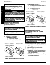
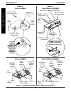
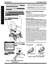
DIRECT MOUNT METHOD (FIGURE 2, 3 AND 4).
1. Install battery terminal cap(s) onto battery cable(s) as
follows (FIGURE 2):
DUAL U1 BATTERIES:
A. ORANGE battery terminal cap onto RED battery
cable.
B. GRAY battery terminal cap onto BLACK battery
cable.
DUAL GROUP 22 NF BATTERIES:
A. RED battery terminal cap onto RED battery cable.
B. BLACK battery terminal cap onto BLACK bat-
tery cable.
FIGURE 2 - CONNECTING BATTERY CABLES -
DIRECT MOUNT METHOD
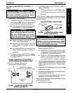
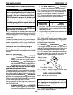
CAUTION
When connecting the battery cables to the
battery(ies), the battery cable(s) MUST be con-
nected to the battery terminal(s)/post(s) as
shown in DETAIL “A” or DETAIL “B” of FIGURE 3
(depending on battery type), otherwise dam-
age to the battery cable may result when in-
stalling battery terminal caps.
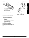
2. Connect battery cable(s) to battery(ies) terminal(s)/
post(s) as follows (DETAIL “A” or DETAIL “B”of FIG-
URE 3, depending on battery type):
A. NEGATIVE (-) BLACK battery cable to NEGA-
TIVE (-) battery terminal/post.
B. POSITIVE (+) RED battery cable to POSITIVE
(+) battery terminal/post.
3. Secure the battery cable(s)/ring terminal(s) to the
battery terminal(s)/post(s), BLACK to NEGATIVE
(-) and RED to POSITIVE (+), with the provided
1/4-20 x 7/8-inch hex flange screw and hex flange
locknut. Securely tighten. (DETAIL “A” or DETAIL
“B”of FIGURE 3, depending on battery type).
4. Verify all battery cable(s)/ring terminal(s) are correctly
installed and securely tightened.
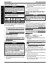
5. Slide terminal cap(s) down battery cable(s) and onto
battery clamps (FIGURE 3).
6. Secure each terminal cap in place with a tie-wrap
(Use tie-wraps 11-1/2-inches long) (FIGURE 3).
NOTE: It will be necessary to trim excess tie-wrap in order to
install the battery box top(s).
7. Install the battery box top(s).
8. Install the battery box(es) into the wheelchair. Refer
to
INSTALLING/REMOVING BATTERY BOX(ES) in
the PROCEDURE 11 - FWD MODELS or PROCE-
DURE 12 - MWD MODELS of this manual.
NOTE: New Battery(ies) MUST be fully charged BEFORE
using, otherwise the life of the battery(ies) will be reduced.
9. If necessary, charge the battery(ies). Refer to
CHARGING BATTERIES in the PROCEDURE 11 -
FWD MODELS or PROCEDURE 12 - MWD MOD-
ELS of this manual.
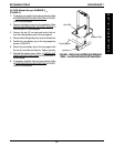
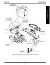
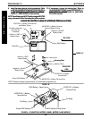
Battery Cable
Battery Terminal Cap
NOTE: Only one (1) battery cable and terminal cap shown
for clarity. Both caps install in the same manner.
INSTALLING BATTERY TERMINAL CAPS