


10
ASSEMBLY
ASSEMBLY
ASSEMBLY OF THE PATIENT LIFT
A
S
S
E
M
B
L
Y
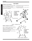
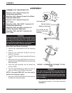
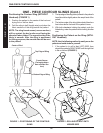
FIGURE 1 - ASSEMBLING THE MAST TO THE
BASE
WARNING
The mast may be removed from the base for
storage or transporting. Each time the mast is
removed and returned to the socket of the base,
the mast MUST be locked into the socket of the
base assembly.
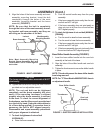
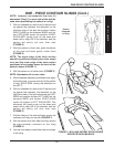
8. Remove the bolt and locknut from the TOP of
the mounting bracket of the mast assembly
(FIGURE 1).
Locking Screw
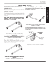
Model No. 9817 - Manual (Crank) Lift
w/Adjustable Width Base
Model No. 9818 - Manual (Crank) Lift w/Offset
Adjustable Width Base
Model No. 9819 - Manual (Crank) Lift
w/"C" Base
Model Nos. 9801, 9805, 9805P - Hydraulic Lift
w/Adjustable Width Base
Model Nos. 9802 and 9806 - Hydraulic Lift
w/Offset Adjustable Width Base
Model Nos. 9803 and 9807 - Hydraulic Lift
w/"C" Base
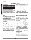
WARNING
Use only Invacare parts in the assembly of this
lift. The base legs, the mast, boom, pump
assembly and the swivel bar are manufactured
to specifications that assure correct alignment
of all parts for safe functional operation.
Base, Mast and Boom Assembly
1. Unpack the components from the shipping
cartons.
2. Remove the LOCKING SCREW from the
bottom of the base.
3. The BOTTOM of the mast assembly will have a
notch.
4. Match the notch at the BOTTOM of the mast as-
sembly with the TABS INSIDE the socket of the
base assembly.
5. Insert the mast assembly into the socket and
onto the TABS.
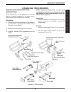
6. Turn the mast assembly to make sure that the
notch is locked on the TABS of the socket.
NOTE: If the mast DOES NOT turn, the mast is
centered and locked in place.
7. Insert the LOCKING SCREW into the bottom of
the base and securely tighten.
Bolt and Locknut
Bottom of mast notch
Top Inside of the
Socket of the Base
Assembly