


Part No. 1056953 43 9000 Series
SECTION 8ANTI-TIPPERS/WHEEL LOCKS
ANTI-TIPPERS/WHEEL LOCKS
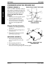
4. Securely tighten the bolt and locknut or socket screws securing the wheel lock to
the wheelchair frame.
5. Engage the wheel lock.
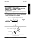
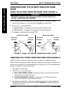
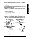
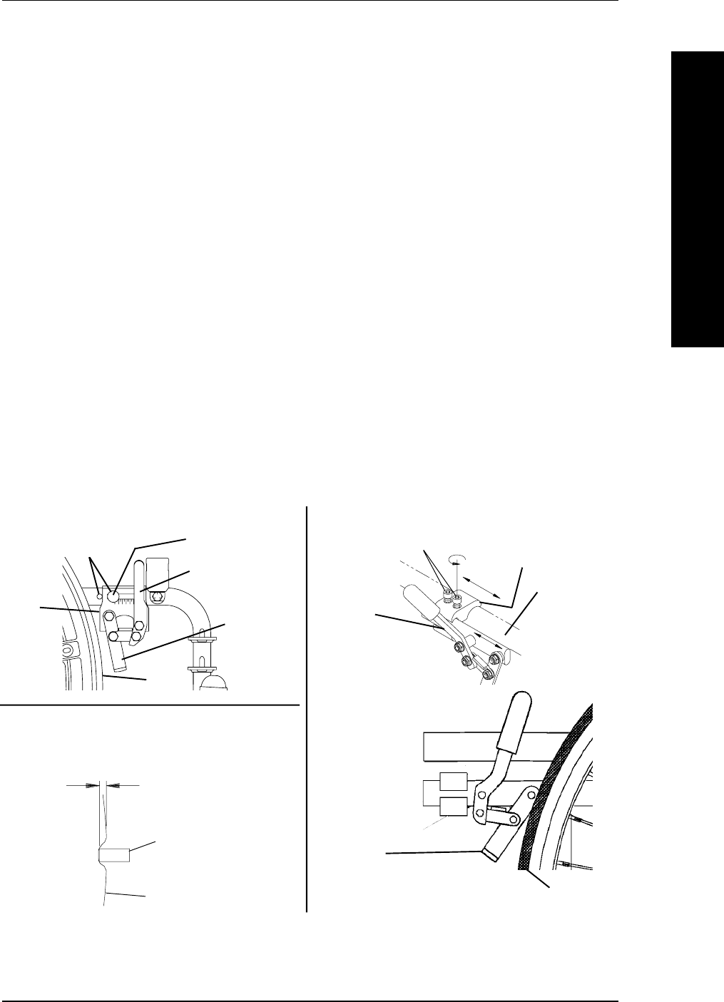
6. Measure the distance the wheel lock is embedded into the tire as shown in DETAIL
"A" of FIGURE 4.
NOTE: Any wheel lock adjustment should embed the wheel lock shoe at least 1/8-inch (3/16-inch
if pneumatic tire) into the tire when engaged.
7. Repeat STEPS 1-6 until the wheel lock shoe embeds the tire 1/8-inch (3/16-inch for
pneumatic tires) and HOLDS the occupied wheelchair in place when pushed.
8. Repeat STEPS 1-7 for the opposite wheel lock.
9. If the measurement of 1/8-inch (3/16-inch for pneumatic tires) can not be achieved,
Perform one (1) of the following:
A. BOLT-ON WHEEL LOCKS - Remove the bolt and locknut that secure the
wheel lock to the wheelchair frame and mount the wheel lock in one (1) of two
(2) mounting positions.
B. CLAMP-ON WHEEL LOCKS - Loosen the two (2) set screws on the wheel
lock clamp and adjust the wheel lock position in the clamp.
10. Repeat STEPS 1-9 until the wheel lock HOLDS the occupied wheelchair in place
when pushed. If the correct measurement still cannot be achieved, contact a quali-
fied technician.
FIGURE 4 - ADJUSTING THE PATIENT OPERATED WHEEL LOCKS
Socket Screws
Wheel Lock
Rear Wheel
Wheel Lock
Shoe
Wheelchair
Frame
Wheel Lock
Handle
Bolt and Locknut
Mounting Positions
Wheel Lock
Shoe
Rear
Wheel
Wheel
Lock
BOLT-ON WHEEL LOCKS CLAMP-ON WHEEL LOCKS
DETAIL "A" - WHEEL LOCK SHOE
ENGAGEMENT
1/8-inch (3/16-inch
pneumatic tires)
Tire
Wheel Lock
Shoe
Wheel Lock
Clamp