


6
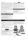
Overload Device
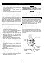
Overload protection is integrated into the motor body and is
standard on -E versions. The overload system is based on
detection of the difference in air pressure between the inlet
and outlet ports. It consists of a valve which is normally
closed. The valve senses pressure at the motor inlet and
outlet and compares the difference between the two
pressures to the index value established by spring
adjustment. A difference in pressure greater than the index
value causes the emergency stop to be activated. This then
exhausts the air and hoist operation stops.
Overload protection is adjusted at the factory to 120% of
the safe working load (SWL). It is also able to operate on
both sides for mining versions with two bottom hooks.
Refer to the "MAINTENANCE" section for adjustment
procedures.
Main Air Shut-off Valve
The main air shut-off valve is completely integrated into the
motor body and is standard on -E versions.
Chain container
1. Check the chain container size to make sure the length of
the load chain is within the capacity of the chain container.
Replace with a larger chain container if required.
2. When a chain bucket is used, Install a chain buffer on the
15th link from the end of the chain.
3. Attach the chain container to the hoist.
4. Run bottom block to the lowest point and run hoist in the
"UP" direction to feed the chain back into the container.
NOTICE
• Allow chain to pile naturally in the chain container.
Piling the chain carelessly into the container by hand
may lead to kinking or twisting that will jam the hoist.
Attaching Limit Stop
1. On hoists without a chain bucket, slide buffer and washer
onto chain.
2. Install limit stop as described under "Chain Container".
3. Run hoist slowly in the "DOWN" direction to verify limit
stop activates cutout.
Storing the Hoist
1. Always store the hoist in a no load condition.
2. Wipe off all dirt and water.
3. Oil the chain, hook pins and hook latch.
4. Place in a dry location.
5. Plug hoist air inlet port.
6. Before returning hoist to service, follow instructions for
hoists not in regular service in the "INSPECTION" section.
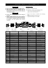
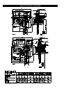
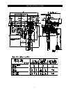
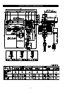
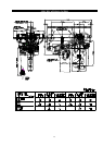
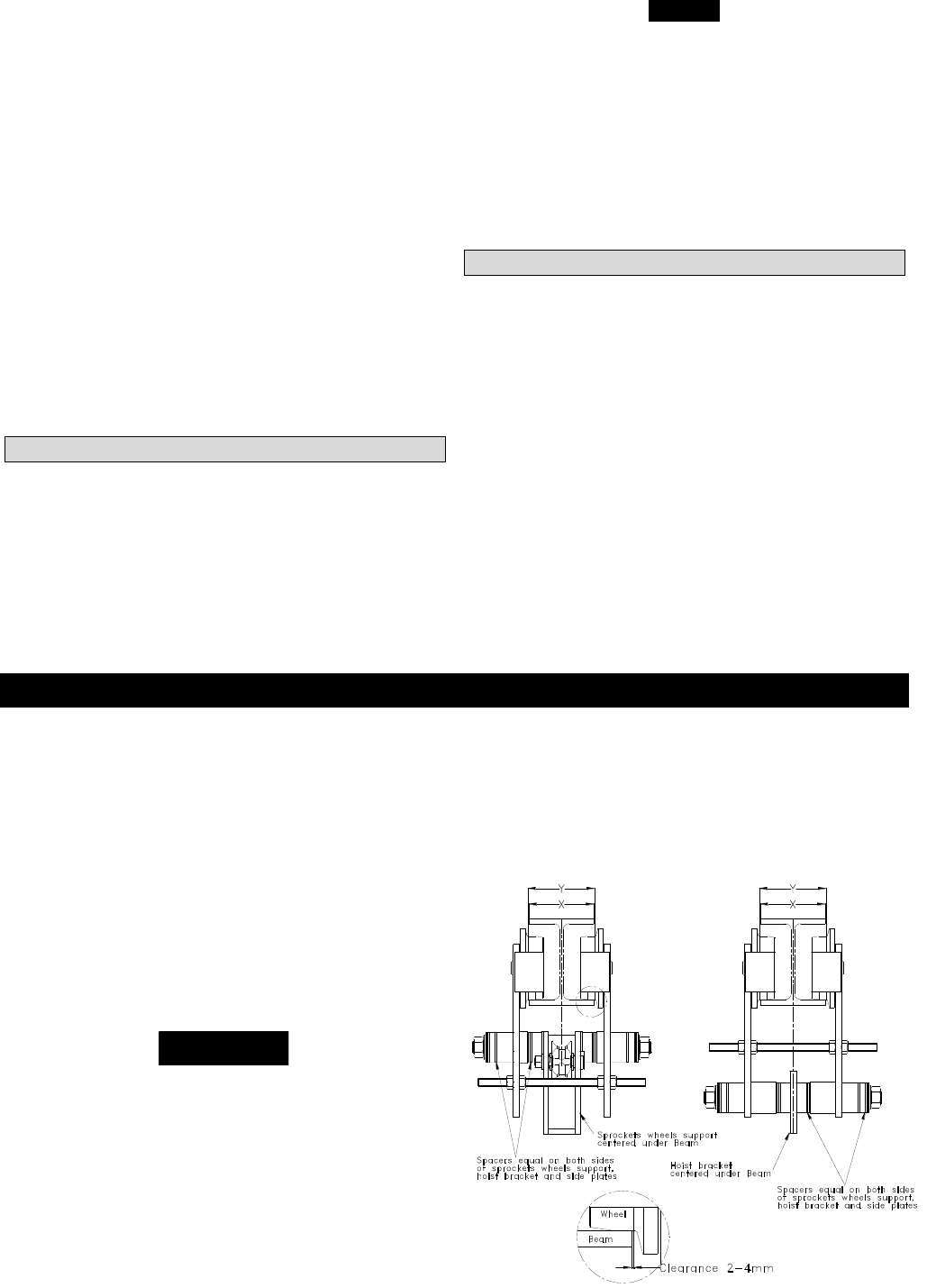
ADJUSTMENT TROLLEY LCA015S/LCA030D
Pre-adjust trolley for installation using Dwg. D5230233 and the
following instructions.
1. Fasten tightening nuts (74) to one end of suspension shaft (75),
using springwashers (73) , apply Loctite® 243 to capscrews
threads.
2. Measure beam flange width and establish required position for
spacers. Install required outside spacers on suspension shaft (75).
3. Thread a nut (66) onto each end of the screw rod (67), as far to
the center as possible.
4. Insert one end of this rod into the side plate and loosely fasten
with another nut (66).
5. Insert suspension shaft through side plate (36).
6. Install an equal number of spacers to each side of hoist
support (35), and sprokets wheels support (58), on suspension
shaft.
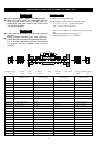
NOTICE
• The total clearance between the beam and the trolley wheel
flanges is 4 to 8 mm when trolley is installed correctly. As
shown in Dwg. D5230233, the difference between dimensions
“X” and “Y” equals the total clearance.
7. Support the assembled portion of trolley on the beam.
8. Install second side plate (37).
9. Place the rest of spacers on the suspension shaft and secure
loosely with nutsand springwashers.
10. Verify trolley wheel to beam total clearance. Adjust spacer
locations until clearance specification is attained (refer to Dwg.
D5230233). Apply Loctite® 243 to nuts and secure in place.
11. Screw inner nuts (66) out until they contact with side plates.
Thread outside nuts (66) onto screw or until tight against side
plates. Check that side plates are perpendicular to beam.
12. Upon completion of installation, ensure trolley beam stops are
installed and conduct initial operating checks as described in
“OPERATION” section. Check that side plates are vertical and
parallel to each other.
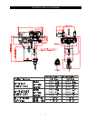
(Dwg.D5230233