


22
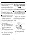
General Trolley Disassembly
NOTICE
• Prior to disassembly note the installation of the adjusting
spacers Install adjusting spacers during
assembly, in the same configuration recorded during
disassembly to ensure beam flange width and hoist position
are retained.
• Prior to disassembly of trolley, first remove trolley motor,
bottom hook ass‟y, load chain and then remove hoist.
For remove the hoist refer to LIFTCHAIN AIR HOIST
Manual ref :SAM0208
Remove the trolley from the beam by removing end stop and after
adequately supporting trolley, run trolley off the beam.
CAUTION
• Support trolley adequately as it comes off beam to prevent
injury and/or damage to equipment. If that is not possible,
loosen or remove only one side plate. Refer to “Side Plate
Disassembly”.
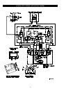
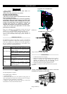
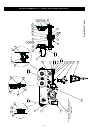
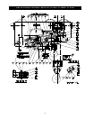
General Disassembly Hoist (LC2A015S/LC2A030D)
Dwg..D6440774
1. Remove the chain and the bottom hook.
2. Remove the chain basket
3. Disconnect all hoses
- Trolley Disassembly
1. Remove one nut (66) from outside of side plate.
No required for LCA015S and LCA030D
2. Remove nuts (28) and, washers (30) from same side
plate. Separate side plate until it is free of beam.
Remove trolley to a clean dust free work area for repair.
1. Remove the other outside nut (66).
2. Remove all nuts (28) and washers (30).
3. Separate the side plate from tie rods (29).
- Plain & Geared Wheel Disassembly
LCA015S/LCA030D
1. Remove retainer ring (49) and pull wheel (50) off of axle
2. Remove retainer ring (47) and pull bearing(s) (48) out of wheel.
a-Large wheel :
1. Remove retainer ring (33) and pull wheel (51) off of axle.
2. Remove retainer ring (31) and pull bearing(s) (32) out of
wheel.
b-Small wheel :
- Return Sprocket Wheel Disassembly
1. Remove nut (20) and pull axle (21) from sprocket wheel
support.
2. Separate sprocket wheel assy from support.
3. Remove Bushing (22) and discard.
- 1.5 and 3 ton Motor Unit Disassembly
1. Disconnect air hoses from power unit.
2. Remove capscrews (18) and lockwashers (19).
3. Remove power unit assembly from trolley side plate.
1.5 and 3 ton Motor Disassembly
Refer to Dwg. D5240240
1. Remove capscrews (220) and lockwashers (221).
2. Remove plate (222). Remove key (218) from spindle shaft
(217).
3. Remove gears (226, 227, 229), washers (223) and thrust race
(228) from motor housing (254).
Spindle assembly (215 through 219) should not be removed from
plate (222) unless repair is required.
4. To remove spindle assembly from plate:
a. Remove retainer ring (219).
b. Tap end of spindle shaft (217) to remove from plate
(222).
5. To remove motor assembly (items 239 through 251):
a. Remove capscrews (238) from brake cone (237).
b. Grasping pinion shaft (231) pull assembly free of motor
housing (254).
6. To disassemble motor assembly (items 239 through 251):
a. Remove nut (230) and separate components (231
through 251).
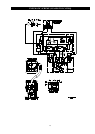
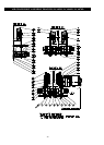
General Disassembly Hoist (LCA030S to LCA250Q)
Dwg..D5240459 / D5440207 / D5960678
1. Remove the chain and the bottom hook.
2. Remove the chain basket
3. Disconnect all hoses
- Trolley Disassembly
1. Remove the screw (41) and extract the motoreducer.
2. Remove the hoist to the support (54).
3. Remove the nut (58) (1 external side of the flange)
4. Remove the nut (51) (3 external side of the flange) and
the external spacers.
5. Remove the sub assembly trolley flange (12) and the
internal spacers
6. Remove the return sprocket wheel support (11)
7. Remove the support (54) and the spacer ring (29).
8. Remove another motorised trolley flange unit (13).
- Plain & Geared Wheel Disassembly
LCA030S/LCA060D/LCA070D
1. Remove the external retainer ring(3) and extract the
rollers wheel (9)
2. ). Remove the internal retainer ring(63) and extract the
ball bearing (33)
Plain & Geared Wheel Disassembly
LCA060S to LCA250Q
1. Remove the nut (50) and extract the roller axle (25).
2. Remove the distance ring (32) and the "O" ring (60).
3. Remove the retainer ring(65) and extract the rollers
bearings (33).
- Return Sprocket Wheel Disassembly
1. Remove the nut (50) and extract the axle (15).
2. Remove the distance ring (17) and extract the return
wheel (14).
3. Remove the rollers bearings (34) and the distance ring
(18).
4. Remove the nut (49) and extract the screw (44).
5. Remove the roller (22).