


20
MAINTENANCE
WARNING
• Never perform maintenance on the hoist while it is
supporting a load.
• Before performing maintenance, tag controls:
DANGER - DO NOT OPERATE -
EQUIPMENT BEING REPAIRED.
• Only allow personnel trained in operation and service of this
hoist to perform maintenance.
• After performing any maintenance on the hoist dynamically
test the hoist to 100% of its rated capacity, in accordance with
ASME B30.16 standards, before returning hoist to service.
Testing to more than 100% of rated capacity is required to set
overload device and may be required to comply with
standards and regulations set forth in areas outside the USA.
• Shut off air system and depressurize air lines before
performing any maintenance.
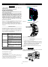
Proper use, inspections and maintenance increase the life and
usefulness of your Ingersoll-Rand equipment. During assembly,
lubricate gears, bearings and shafts with applicable lubricants.
Use of a thread locking compound and/or thread lubricant on
capscrew and nut threaded areas helps prevent corrosion of
components.
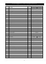
Maintenance Intervals
The Maintenance Interval Chart below is based on intermittent
operation of equipment for eight hours each day, five days per
week. If the equipment is in operation for more than eight hours a
day or is operated in severe applications or environments, more
frequent maintenance should be performed.
INTERVAL
MAINTENANCE CHECK
Start of each shift
Make a thorough visual inspection of the
hoist for damage. Do not operate the hoist if
damage is found.
Operate in both directions. Hoist must
operate smoothly without sticking, binding
or abnormal noises.
Check the operation of the brake.
Quarterly
Remove, clean or replace muffler in top of
gear housing.
Yearly
Inspect the hoist gearing, shafts and bearings
for damage or wear. Repair or replace as
necessary.
Check all of the supporting members,
including the trolley if used. Repair or
replace as required.
Adjustments
Brake
No brake adjustment is required.
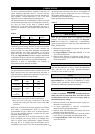
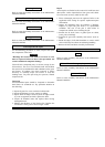
Annual Maintenance is limited to:
1. A general cleaning.
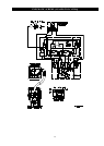
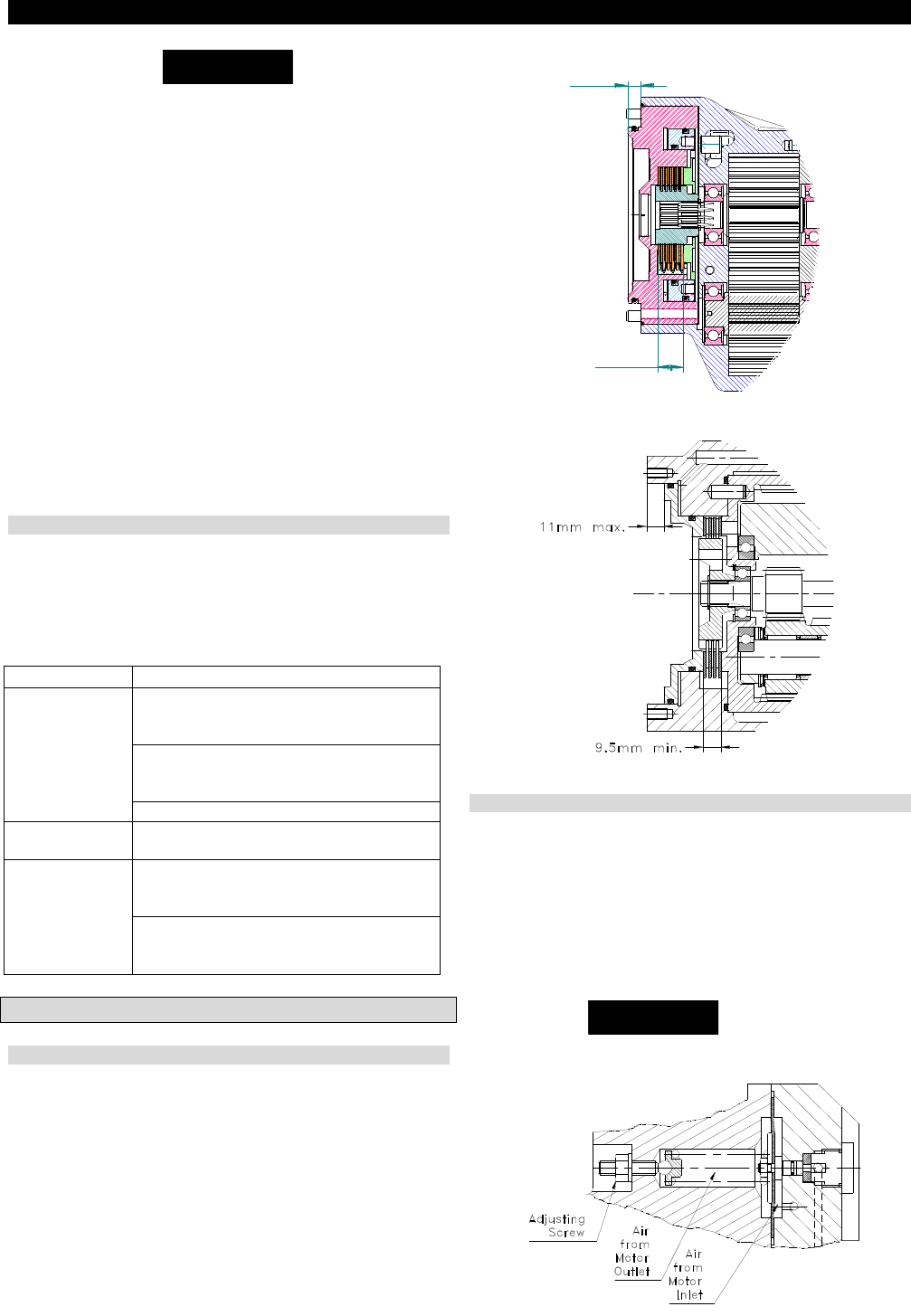
2. The friction discs have a 0.2 mm (0.079 in.) deep groove on
each side. Replace the friction discs if the grooves are no longer
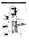
visible. Refer to Dwg. D6440775 or D4120242.
3. Measure total brake and steel plate stack up. Check that
measurement is not less than minimum shown.
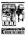
LC2A015S and LC2A030D Hoists
(D6440775)
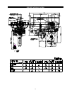
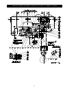
LCA030S TO LCA250Q Hoists
(Dwg. D4120242)
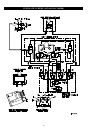
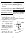
Overload Device
1. Connect the hoist to the air supply.
2. Release the locknut and turn the adjustment screw in order to
increase or decrease the SWL (increase the SWL by
tightening the adjustment screw). The adjustment must be
made for an overload of 20% maximum of the SWL.
3. Tighten the locknut securing the adjustment screw.
4. Check hoist operation at rated load. If necessary repeat the
adjustment.
NOTICE
OTICE
• Do not change factory settings unless hoist is tested and
recertified at an authorized repair facility.
(Dwg. D4120413)
A
A
B
D6440775
14,5 mini
7,5 mini