


6 Form 10590149-Edition 2
- Assemble motor to housing.
- Lubricate and assemble o-rings (35) into counterbore
of end plate (38).
- Assemble new gasket (31) and head to housing.
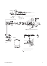
Brake and Gearing Disassembly
- Remove two screws (96) and housing cap (95).
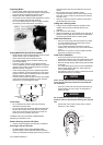
- Carefully slide brake spring (94) part way off brake
shoes (92) and using brake spring spreader (33541),
remove brake spring (94).
CAUTION
remove brake spring (94) with due regard for safety as
spring is assembled with considerable tension.
- Remove brake shoes (92) and steel balls (91).
- Align hole in brake wheel (93) with hole in end plate
(89) and insert a punch or pin thru holes to secure
brake wheel.
- Remove cotter pin (74), nut (99) and washer (100).
- Remove brake wheel (93).
- Remove roll pin (61) and brake block (60).
- Remove four screws (103) and washers (104).
- Place blade type screwdrivers, or similar tool, at
opposite sides behind edge of end plate (89) and pry
out on end plate to remove from housing.
- Remove gearing assembly.
- Remove retaining rings (70) and (82).
- Push on threaded end of shaft (72) and remove out
opposite end of gear carrier (75).
- Remove bearing (80), spacer (79) and shafts (78),
releasing gears (77) and bearing races (76).
- Remove retaining ring (83) and bearing (81).
- Remove four shoulder screws (101) and washers
(102) and fixed ring gear (84).
- Remove seal (88) for replacement only.
Assembly
Brake and Gearing Assembly
- Lubricate and assemble six o-rings (86) into
counterbores of fixed ring gear (84).
- Assemble seal (88) to end plate (89) - lip of seal facing
out.
- Assemble wave washer (87) and end plate (89) to
fixed ring gear (84) and secure with four washers (102)
and shoulder screws (101),
- Assemble gears (77), bearing races (76) and shafts
(78) to gear carrier (75).
- Assemble spacer (79) to gear carrier aligning spacer
with notched ends of shafts (78).
- Lubricate bearings (73) and (80) with NLGI #1 “EP”
grease (33153) and assemble to gear carrier (75).
- Lubricate bearing (71) with NLGI #1 “EP” grease
(33153) and assemble to shaft (72).
- Assemble shaft (72) to gear carrier (75) and secure
with retaining ring (70).
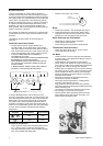
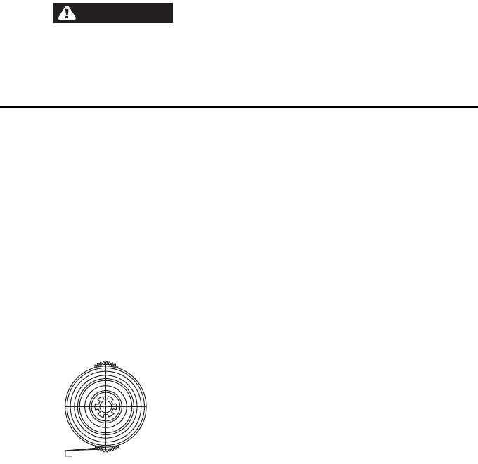
IMPORTANT: punch marks on gears (77) indicating
aligned teeth must be held in alignment with punch
marks on gear carrier (75) when shaft (72) to assembled
to gear carrier.
- Lubricate bearing (81) with NLGI #1 “EP” grease
(33153) and assemble to shaft (72).
- Assemble retaining ring (82) and (83) to shaft (72).
- Assuming o-ring (53) and ring gear (55) are
assembled to housing (see housing assembly);
assemble gearing into ring gear (55).
- Lubricate and assemble o-ring (54) over fixed ring
gear (84) and slide up to end plate.
- Assemble fixed ring gear and end plate to gearing and
housing. Use reasonable caution so as not to damage
seal (88) in end plate.
- Secure end plate and components to housing with
washers (104) and screws (103).
- Assemble brake wheel (93) to shaft (72) and secure
with washer (100), nut (99) and cotter pin (74).
- Assemble control rod (59) thru housing, hangers (62)
and control arm (68).
- Secure control arm (68) to rod with roll pin (69).
- Assemble brake block (60) and roll pin (61) to control
arm (59).
- Assemble screw (90), balls (91), brake shoes (92) and
brake spring (94).
- Assemble housing cap (95) and secure with two
screws (96). See brake adjustment, page 2.
- Fill gearing oil chamber with 6 to 7 ounces (to lower
plug hole level) “EP” gear oil (40164).
Housing Disassembly
- Remove head, motor and gearing sections.
- Remove screws (67), washers (66) and plate (65).
- Place brass or wood block in pocketwheel cavity to
prevent shaft (50) from turning.
- Remove nut (58), washer (57), o-ring (56) and ring
gear (55).
- Remove retaining ring (46) from “motor end” of
housing.
- Remove shaft (50) with bearing (47).
- Remove pocketwheel (64) and chain guide (63).
- Remove seal (52) for replacement only.
Housing Assembly
- Assemble bearing (47) and retaining ring (46) to “brake
end” of housing.
- Assemble chain guide (63) and pocketwheel (64) to
housing.
NOTE: part number stamped on face of pocketwheel
must face “motor end” of housing.
- Assemble retaining ring (48) and bearing (47) to shaft
(50).
- Insert shaft (50) into housing and thru pocketwheel
(64) and bearing (47).
- Assemble retaining ring (46) to housing.
- Assemble plate (65), washers (66) and screws (67) to
housing.
- Assemble new seal (52) into housing with lip of seal
facing out.
- Lubricate and assemble o-ring (53) into groove in
housing.
- Assemble ring gear (55), o-ring (56), washer (57) and
nut (58).
- Assemble motor, gearing and head sections to hoist.
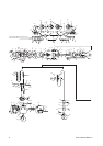
PUNCH MARKS ON GEARS AND PUNCH MARK
ON CARRIER MUST BE IN ALIGNMENT