


Form 10590149-Edition 2 5
Maintenance
Dissassembly
Head Disassembly
To remove head section from housing without disassembling
head components, remove head with control rod (59)
attached to gear (25). To accomplish this -
- Remove two screws (96) and housing cap (95).
- Drive out roll pin (61) and remove brake block (60).
- Drive out roll pin (69) from control arm (68).
- Remove six screws (22) and washers (23).
- Remove head section and control rod from housing as
one unit.
To disassemble head components without removing head
section from hoist:
- Remove two screws (96) and housing cap (95).
- Drive out roll pin (69) from control arm (68).
- Drive out roll pin (26) from gear (25) and drive control
rod (59) back thru gear (25) and remove gear.
- Remove adapters (19), valves (17) and (29) and valve
body (15).
- Remove set screws (24) and regulator valves (28).
CAUTION
do not attempt to adjust or remove regulator valves (28)
from spark-resistant hoist models - these valves are
pre-set at fatctory.
- Remove adapter (1) and screen (2).
- Remove retaining ring (4), swivel (3), swivel body (6)
and screen (8).
- Remove two screws (9), washers (10), exhaust
deflector (11), screen (12) and muffler filler (13).
NOTE: When reassembling head to housing a new Gasket
(31) must be installed. Tighten Screws (22) to approximately
60 in-lbs. torque. When tightening these screws it is
recommended that an air line be attached to the air inlet and
the hoist operated to insure that no binding of the motor
occurs. Tighten screws alternately and gradually until desired
torque is reached without binding of motor. Lubricate all
O-Rings with O-Ring lube (36460) before assembling. Insure
O-Ring (32) is properly positioned in head.
- Assemble valve body (15) into head - see “Timing of
Head”, this page.
- Assemble o-rings (27) to regulator valves (28).
- Assemble regulator valves (28) to head and secure
with set screws (24). NOTE: groove in regulator valve
must be aligned to accept set screw. See setting hoist
speed, page 2.
- Assemble muffler filler (13), screen (12) and exhaust
deflector (11) to head and secure with washers (10)
and screws (9).
- Clean and assemble screen (8) to head.
- Assemble o-rings (5) and (7) to swivel body (6) and
assemble body to head.
- Assemble swivel (3) to swivel body and secure with
retaining ring (4).
- Clean and assemble screen (2) and inlet adapter (1) to
swivel.
- Fill oil reservoir in head with spindle oil 29665.
Pendent Control Disassembly
- Remove pendent hoses from fittings (156) and (165).
- Remove adapter (166) from head releasing strain
cable.
- Remove screws (168), springs (170) and valves (171).
Pendent Control Assembly
- Lubricate o-rings (172) and assemble to valves (171).
- Assemble valves (171) and springs (170) to handle.
- Lubricate o-rings (169) and assemble to screws (168).
- Assemble screws (168) to handle securing valve
components.
Pendent Cylinder Disassembly
- Unthread cylinder (157) from adapter (163).
Pendent Cylinder Assembly
- Assemble piston rod (160) to piston (159).
- Lubricate and assemble o-ring (158) to piston (159).
- Lubricate and assemble o-rings (162) and (164) to
adapter (163).
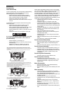
Motor Disassembly
- Remove head section - see “Head Disassembly”.
- Remove motor from housing.
- Remove retaining ring (36); motor assembly will come
apart,
Motor Assembly
- Lubricate bearings (37) with NLGI #1 “EP” grease
(33153) and assemble bearings to end plate (38) and
(43) - shielded side of bearing facing out.
- Assemble end plate (43) to spindle (45) and slide up to
shoulder of spindle.
- Assemble key (44) to key slot in spindle (45).
- Assemble rotor (41) over spindle aligning key way and
key (44).
- Assemble cylinder (39) over rotor (41) and insert
blades (42) into blade slots of rotor - straight side of
blade out.
- Assemble end plate (38) to spindle and align hole in
end plate with roll pin (40).
- Secure assembled parts to spindle with retaining ring
(36).
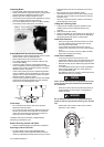
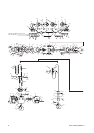
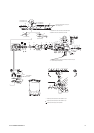
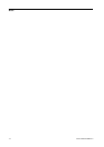
UP DN
ENDS OF VALVE BODY FLUSH WITH BUSHING
IDENTIFICATION MARK "x" ON END OF VALVE BODY
TIMING GROOVES
ON VALVE BODY
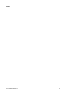
UP DN
GEAR [25]
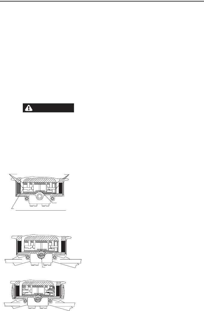
UP DN
STEP 1 :- POSITION HOIST SO YOU ARE FACING END WITH AIR INLET, WITH VALVE
PARTS AND GEAR [25] REMOVED, PLACE VALVE BODY IN VALVE OPENING. INSERT
FINGER IN EACH END OF VALVE OPENING AND ALIGN END OF VALVE BODY WITH ENDS
OF BUSHING.
NOTE: VALVE BODY MUST BE INSTALLED WITH IDENTIFICATION MARK AS SHOWN.
STEP 2 :- WITH BRAKE RELEASE BLOCK ASSEMBLED TO CONTROL ROD, INSERT ROD
THROUGH BRAKE END OF HOUSING, THROUGH CONTROL ARM [68] AND ON THROUGH
HOUSING STOPPING BEFORE ROD PROTRUDES FROM HEAD.
A
SSEMBLE GEAR [25] TO HEAD ALIGNING CENTER TOOTH OF GEAR BETWEEN TWO
GROOVE MARKINGS ON THE VALVE BODY AS SHOWN.
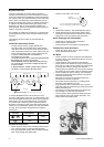
A
SSEMBLE CONTROL ROD THROUGH GEAR AND SECURE WITH ROLL PIN [26]. SECURE
CONTROL ARM TO ROD WITH ROLL PIN [69].
STEP 3 :- ASSEMBLE O-RINGS [16] TO VALVES [17] AND [19] AND ASSEMBLE VALVES
INTO HEAD AS SHOWN. ASSEMBLE O-RINGS [18] TO ADAPTERS [29] AND O-RINGS
[20] TO VALVE CAPS [21] AND ASSEMBLE TO HEAD.