


2 Form 10590149-Edition 2
Safety Information
Operating Precautions
To aid the operator’s understanding of proper and safe use of
hoists, the publication “OVERHEAD HOISTS”,
ANSI B30.16-1981, can be purchased from:
American Standards Institute, Inc.
1430 Broadway
New York, New York 10018
• Do not use the hoist described in this manual to lift or
transport humans.
• Never try to lift a load heavier than the rated capacity of
the hoist.
• Operate hoist with caution. Operator should have a good
attitude toward safety.
• Always follow “proper operating” instructions given in this
manual.
• Allow only people who have received training in “proper
hoist operation” to operate hoists.
• Follow all operating and routine inspection procedures
prescribed in this manual.
• Operator of hoist shall operate hoist in a position that will
not be hazardous to his health.
• Do not attempt to operate hoist if it is not operating
properly.
• Before operating hoist, all routine inspection and
lubrication procedures should be completed.
Lubrication
Routine Lubrication Requirements
Lack of or an excessive amount of lubrication will affect the
performance and life of this tool Use only recommended
lubricants at below time intervals:
EVERY 8 HOURS OF TOOL OPERATION -fill lubricator
reservoir with spindle oil (29665). If an in line or air line
lubricator is not used, fill oil reservoir of built-in oiler of hoist
head.
EVERY 80 HOURS OF HOIST OPERATION - Grease fittings
in lower BLOCK HOOK ASSEMBLY and TROLLEY
WHEELS with NLGI #1 grease 33153).
EVERY 160 HOURS OF HOIST OPERATION - Fill oil
reservoir in GEAR CHAMBER with “EP” gear oil (40164).
Coat load chain of hoist with EP” gear oil (40164).
Air Supply Requirements
For maximum operating efficiency, the following air supply
specifications should be maintained to this hoist.:
• AIR PRESSURE - 90 PSIG (6 bar)
• AIR FILTRATION - 50 micron
• LUBRICATED AIR SUPPLY
• HOSE SIZE - l/2” (13 mm) I.D.
An AR0 model 128241-800 airline FILTER/REGULATOR/
LUBRICATOR (F-R-L) is recommended to maintain the
above air supply specifications.
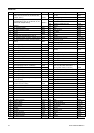
Recommended Lubricants
After disassembly is complete all parts, except sealed or
shielded bearings, should be washed with solvent. To
relubricate parts, or for routine lubrication, use the following
recommended lubricants:
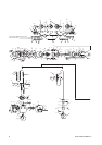
Operation
Suspending Hoist Adjusting Brake
Always select an overhead support capable of supporting
combined weight of hoist, trolley, and hoist’s load capacity.
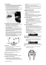
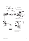
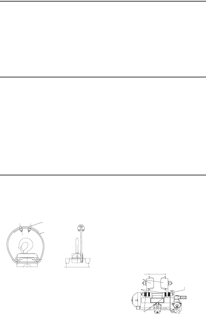
Hook Suspended Models
• Upper hook should be firmly seated in center of hook
saddle and that safety latch is closed.
• 43059 secondary support cable is recommended.
(Dwg. )
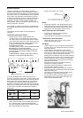
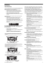
Trolley Suspended Models
• Be sure TROLLEY WHEELS are compatible with beam
being used.
• Width between outside of TROLLEY WHEELS should be
the width of beam flange + l/2”.
• If 43111 - 90’ ADAPTER is used, mount to hoist before
attempting to install trolley.
• Width is varied by using SPACERS between the hoist
body and the trolley SIDE PLATES.
• Insert an equal number of SPACERS on each inside of
the trolley SIDE PLATES until beam flange + l/2”
measurement is reached. SIDE PLATES must be
vertical.
• Insert SHAFTS (43009) through hoist, or adapter if used,
and trolley SIDE PLATES.
• Position trolley and hoist assembly on beam.
• Put an equal number of SPACERS on each end of
SHAFTS (43009) with lock washer being last.
• Tighten nuts on SHAFTS (43009). SHAFTS should
extend all the way through the NUTS.
• Move trolley over entire length of beam. If it appears the
trolley SIDE PLATES can be moved closer together and
freedom of movement will be maintained, remove an
equal number of SPACERS from inside the SIDE
PLATES and assemble these SPACERS to the outside of
the SIDE PLATES.
• Tighten NUTS to 25-30 ft. Ibs.
• Connect sufficient length of air hose to reach the
maximum travel distance of trolley.
Where Used ARO Part# Description
Air Motor 29665 1 qt. Spindle Oil
Gears and Bearings 33153 5 lb. “EP” - NLGI #l1Grease
“O” Rings & Lip Seals 36460 4 oz. Stringy Lubricant
Gearing Oil Chamber 40164 1 qt. “EP” Gear Oil
42631 CLAMP (2)
43066 RESTRAIN-
ING CABLE (5/16”
DIA. X 3½ FT. LONG
AIRCRAFT CABLE)
EQUAL NO. OF SPACERS
EQUAL NO. OF SPACERS
WIDTH OF BEAM
FLANGE PLUS 1/2”
TIGHTEN NUTS 46049
25 TO 30 FT. LBS. TORQUE
SIDE PLATES MUST
BE VERTICAL