


Y8610U INTERMITTENT PILOT RETROFIT KIT
17 68-0291—03
TROUBLESHOOTING
WARNING
Fire, Explosion, or Electrical Shock Hazard.
Can cause severe injury, death or property damage.
Do not attempt to modify the physical or electrical
characteristics of this device in any way. Replace it if
troubleshooting indicates a malfunction.
IMPORTANT
1. The following service procedures are provided as a
general guide. Follow appliance manufacturer’s ser-
vice instructions if available.
2. Meter readings between the gas control and ignition
control module must be taken within the trial for igni-
tion period. Once the ignition control module shuts off,
it must be reset by setting the thermostat down for at
least 30 seconds before continuing.
3. If any component does not function properly, make
sure it is correctly installed and wired before replacing
it.
4. The ignition control module and the gas control can-
not be repaired. If either malfunctions, it must be
replaced.
5. Only trained, experienced service technicians should
service intermittent pilot systems.
6. After troubleshooting, check out the system again to
be sure it is operating normally.
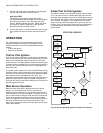
Troubleshooting Sequence
The general troubleshooting sequence is as follows:
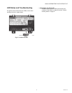
1. Refer to “LED Status and Troubleshooting” on page 19
for LED status codes.
2. Perform the “Checkout” on page 15 as the first step in
troubleshooting.
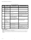
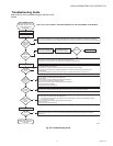
3. Check the Troubleshooting Guide (Fig. 22 on page 21)
to pinpoint the cause of the problem.
4. If troubleshooting indicates an ignition problem, see Igni-
tion System Checks below to isolate and correct the
problem.
5. Following troubleshooting, perform the “Checkout” on
page 15 again to be sure system is operating normally.
Ignition System Checks
Step 1: Check Ignition Cable.
Make sure:
1. Ignition cable is not damaged, cracked, burned, or dirty.
Replace if necessary.
2. Ignition cable does not run in contact with any metal sur-
faces.
3. Ignition cable is no more than 36 in. (0.9 m) long.
4. Connections to the ignition control module and to the
igniter or igniter-sensor are clean and tight.
5. Ignition cable provides good electrical continuity.
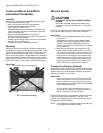
STEP 2: Check Ignition System Grounding.
Nuisance shutdowns are often caused by a poor or erratic
ground. A common ground, is required for the ignition control
module and the pilot burner bracket.
1. Check for good metal to metal contact between the pilot
burner bracket and the main burner.
2. Check the ground circuit from the GND (BURNER) termi-
nal on the ignition control module to the pilot burner.
Make sure connections are clean and tight. If the wire is
damaged or deteriorated, replace it with 14 to 18-gauge,
moisture-resistant, thermoplastic insulated wire with
221°F (105°C) minimum rating.
a. Check the ceramic flame rod insulator for cracks or
evidence of exposure to extreme heat, which can
permit leakage to ground. Replace pilot burner/
igniter-sensor and provide shield, if necessary.
b. If the flame rod or bracket is bent out of position,
restore to correct position.
STEP 3: Check Spark Ignition Circuit.
You will need a short jumper wire made from ignition cable or
other heavily insulated wire.
1. Close the manual gas valve.
2. Disconnect the ignition cable at the SPARK terminal on
the ignition control.
WARNING
Electrical Shock Hazard.
Can cause severe injury, death or property damage.
When performing the following steps, do not touch the
stripped end of jumper or SPARK terminal. The ignition
circuit generates over 10,000 volts and electrical shock
can result.
3. Energize the ignition control module and immediately
touch one end of the jumper firmly to the GND terminal
on the ignition control module. Move the free end of the
jumper slowly toward the SPARK terminal until a spark is
established.
4. Pull the jumper slowly away from the terminal and note
the length of the gap when sparking stops. Check Table
8.
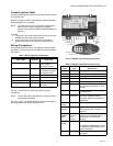
Table 8. Arc Troubleshooting.
Arc Length Action
No arc or arc less
than 1/8 in. (3 mm)
Check external fuse, if provided.
Verify power at the ignition control
module’s control input terminal.
Replace control if fuse and power are
okay.
Arc 1/8 in. (3 mm)
or longer
Voltage output is okay.