Y8610U INTERMITTENT PILOT RETROFIT KIT
68-0291—03 12
Locate and Mount the S8610U
Intermittent Pilot Module
Location
Identify a mounting location for the S8610U ignition control.
The mounting location must provide:
— Good, clear access to the field wiring terminals.
— Operating ambient temperatures between
-40°F (-40°C) and 165°F (74°C).
— Direct the cable route to the pilot burner. The cable route
must be 30 inches (762 mm) or less and not expose the
cable to excessive heat.
— Relative humidity below 95% non condensing.
— Protection from water, steam or corrosive chemicals that
are used to clean the appliance.
— Protection from dripping water, such as from an overfilled
humidifier or from condensation.
— Protection from dust or grease accumulation.
Mounting
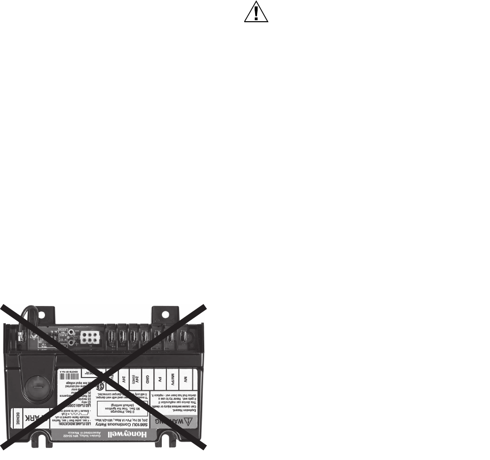
Mount the ignition control module with the terminals down to
protect them from dripping water and dust. The control module
can also be mounted with the terminals on either side. Do not
mount with the terminals pointing up. Fig. 14 illustrates the
incorrect mounting position. Use the S8610U as a template to
mark the mounting hole pattern. Drill new holes, as required.
Fasten securely with four – No. 6-32 machine screws, or No. 8
sheet metal screws, or 8-18 x 5/8 Pan Head tapping screws.
IMPORTANT
Do not mount with terminals facing up.
Fig. 14. Incorrect mounting.
Wire the System
ELECTRICAL SHOCK OR EQUIPMENT DAMAGE
HAZARD.
Disconnect the power supply before making wiring
connections to prevent electrical shock or equipment
damage.
All wiring must comply with local codes and ordinances. Refer
to Fig. 15 and Table 5 on page 13 for typical connections.
IMPORTANT
1. As shown in the wiring diagrams, a common ground
is required on:
The pilot burner mounting bracket, and the GND
(BURNER) terminal on the ignition control module.
Failure to use the GND (BURNER) terminal may
result in intermittent loss of spark and/or loss of flame
current sensitivity.
2. Make sure the transformer has adequate VA. The
ignition control module requires at least 0.1 A at 24
Vac. Add the current draws of all other devices in the
control circuit, including the pilot and main valves in
the gas control, and multiply by 24 to determine the
total VA requirement of these components. Add this
total to 2.4 VA (for the ignition control module). The
result is the minimum transformer VA rating. Use a
Class II transformer if replacement is required.
Connect Vent Damper (Optional)
If the ignition control module is to be used with an existing vent
damper and harness to be connected to the module’s integral
damper connector in an atmospheric appliance, perform the
following to connect it to the module:
IMPORTANT
After the initial power-up, the ignition control module
senses the presence of the vent damper connection.
If the vent damper is connected, the ignition control
module permanently configures itself to operate only
with the damper connected.
Once an ignition control module powers up with a
vent damper connected, the module will not function
without a vent damper being connected.
Using the wiring harness on the appliance, insert the matching
6-pin plug into the connector labeled P1 (see Fig. 15 on
page 13) on the S8610U ignition control module and connect
the other end to the vent damper.
NOTE: The connector (P1) accepts a Molex 03-06-2061 plug
on the existing vent damper harness.


