


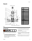
Rebuild
332089B 21
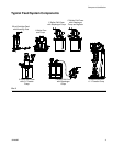
Build the Divorced Section and Mount to the Main
Body
5. Place lubricated U-cup Seal (8) lip side up into the
Divorced Section (10). Place the Washer (7) over it,
and reinstall the Retaining Ring (6).
6. Lubricate and insert the Metering Rod (11) into the
Divorced Section (10) from the bottom and push up
carefully through the U-cup seal (8).
7. Install the Seal Cup (12) into the Divorced Section
(10) over the Metering Rod (11) and slide the lubri-
cated Posipak Seal (13) over the Metering Rod
keeping the O-ring side of the Posipak facing down.
The ends of the Metering Rod (11) should be pro-
jecting from the upper and lower ends of the
Divorced Section.
8. Lubricate the dispense sleeve bore in the Main
Body (27). Insert the Dispense Sleeve (14) into the
Main Body (27). Check for threads that may be in
the inside of the sleeve due to tapping during
removal and make sure these are at the top.
9. Install a lubricated O-ring (15) around the Dispense
Sleeve (14).
10. Holding the Divorced Section (10) and using the
projecting Metering Rod (11) as a guide slide the
Metering Rod (11) into the Dispense Sleeve (14)
and install the Divorced Section (10) against the
Main Body (27). Install the Screws (16).
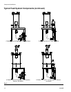
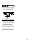
Mount the Valve End Caps to the Seal Plate Cups
11. Install a lubricated U-cup Seal (4) onto the left Spool
Shift Piston (21) with lip side out as shown. Lubri-
cate the bore in the End Cap (19). Slide the piston
into the left End Cap (19) tucking the lip of the seal
into the End Cap carefully.
12. Install the Piston/End Cap onto the left Seal Plate
Cup (26) using four Screws (18). Tighten the screws
in a cross patter n gradually to prevent binding due
to misalignment (like you would tighten lug nuts on a
car tire).
13. Push the Spool into the left side until it contacts the
piston.
14. Repeat steps 13 and 14 for the right side.
Install the Drive Cylinder
15. Install lubricated O-ring (5) on top of the Divorced
Section (10).
16. Install two lubricated U-cup Seals (4) onto the Dis-
pense Piston (3) with the upper seal lip up and the
lower seal lip down as shown.
17. Lubricate the bore of the Drive Cylinder End Cap
Assembly (2) and insert the Dispense Piston (3)
flush with the end of it, tucking the lip of the upper
U-cup Seal (4) so that it is not damaged.
18. Slide the Metering Rod (11) into the key slot on the
piston and slide the Drive Cylinder End Cap Assem-
bly (2) down onto the Divorced Section (10) and
carefully over the O-ring (5).
19. Align the screw holes in the Drive Cylinder End Cap
Assembly (2) with the corresponding holes in the
Divorced Section (10) and install the four Screws
(1). Tighten the screws in a cross pattern gradually
to prevent binding due to misalignment (like you
would tighten lug nuts on a car tire).
20. Install the short air lines on the left and right sides of
the valve.
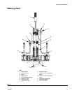
Install the Needle Block Assembly
21. Install any removable needles that were previously
removed.
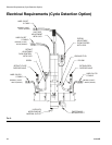
22. If your valve has cycle detection, slide the cycle
detection sensors into the slots on the end caps and
secure with the set screws. Do not overtighten the
set screws as the sensors may be damaged.
23. Connect the air lines.
24. Perform the Dry Run, Loading & Priming and Output
Verification procedures. Perform Operation Adjust-
ment procedures if required.