


30
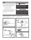
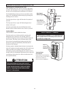
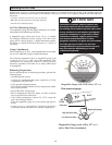
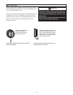
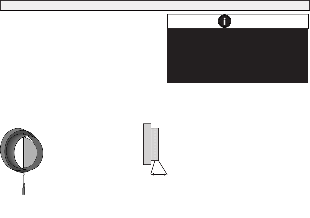
Push and turn with slotted
screwdriver. Damper
automatically locks when
pressure is released.
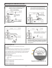
Observe the location of the screws
when connecting ductwork to the
collar. Screws should be located no
further than 1/2” from the outside
edge of the collar and they should
be no longer than 3/4”.
1/2”
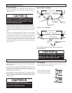
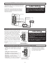
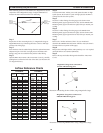
Balancing Dampers
Installations where the HRV is ducted directly to
the return of the furnace/Air Handler may
require additional dampening on the fresh air to
building duct.
This is due to the high return static pressures
found in some furnace installations.
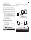
The FC155HRV and FC200HRV models have factory installed
Balancing Dampers located in the “Fresh Air to Building” and
“Stale Air from Building” collars.
All other units require the installation of balancing dampers (not
included) in the “Fresh Air to Building” and “Stale Air from
Building” ductwork. Refer to the installation diagrams in this
manual for the Simplified, Partially Dedicated, and Fully
Dedicated systems.
NOTE
Illustration of Adjusting the Factory Installed
Balancing Damper
Illustration of Connecting ductwork to the
Balancing Damper Collars