


28
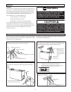
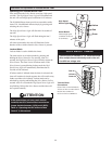
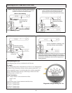
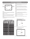
Balancing the Air Flows with a Pitot Tube
STEP 1. D
rill a 3/16” hole in the duct (ideally 3 feet downstream of
a
ny elbows or bends and 1 foot upstream of any elbows
or bends) in the Fresh Air and Stale air streams.
Stale Air From Building
Balancing
Damper
Balancing Damper
Fresh Air to Building
Drill 3/16” holes in
Stale & Fresh Air
ducts.
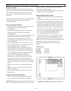
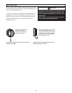
STEP 2. Insert the Pitot tube with the tip facing towards the air
stream in the Stale Air From Building air stream. Move
the Pitot tube around in the duct (facing towards the
airflow) and take an average reading. Record the reading.
Magnehelic Gauge must be level.
Pitot tube tip facing
t
owards the air stream.
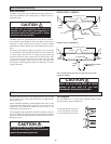
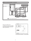
STEP 3. Repeat Step 2 to measure the Fresh Air to Building duct.
Magnehelic Gauge
must be level.
Pitot tube tip facing
towards the air stream.
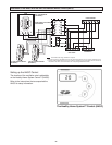
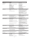
STEP 4.
A) Review the readings and damper down the duct with the
highest duct velocity pressure. Repeat Step 2 and Step 3
until both ducts show indentical readings. For this example,
the Fresh Air to Building air stream has the highest duct
velocity pressure.
B) Upon completion of balancing, seal
the holes (foil tape recommended).
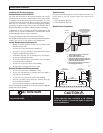
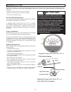
Determining the cfm
After balancing the air flows, calculate the cfm flow rate.
Example
This example shows how to determine the air flow for a 6” diameter duct.
As shown in the illustration, the duct velocity pressure reads 0.025” w.c.
on the magnehelic gauge. Use the chart that came with the magnehelic
gauge to determine a duct velocity of 640 feet per minute for a duct
velocity pressure of 0.025” w.c.
Cfm Calculation
cfm = feet per minute x cross section area of duct
= 640 x 0.196
= 125
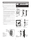
Cross Section Area of some common round duct sizes:
0.087 for 4” diameter duct
0.136 for 5” diameter duct
0.196 for 6” diameter duct
0.267 for 7” diameter duct
Magnehelic Gauge reading .025” w.c.