


5
MODEL 430 DO SECTION 2.0
INSTALLATION
SECTION 2.0
INSTALLATION
2.1 GENERAL. This section provides instructions for
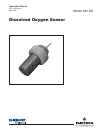
the Model 430 Dissolved Oxygen Sensor.
2.2 UNPACKING AND INSPECTION. Inspect the ship-
ping container and remove the sensor. Carefully check
the sensor and its associated hardware for any dam-
age. Report any damage to the carrier immediately.
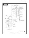
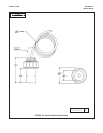
2.3 MECHANICAL INSTALLATION. The sensor
comes in four different configurations. Follow the
instruction for the configuration being installed. See
Figure 2-2 for dimensions. Figure 1-2 illustrates
optional bracket assembly for sensor installation in
tanks or ponds.
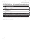
2.4 Electrical Installation. Connect the sensor to the
transmitter as shown in Table 2-1.
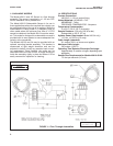
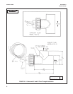
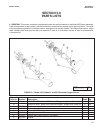
2.3.1 Codes 01 and 02 (see Figure 2-1). These config-
urations are for flow through measurements. Install the
tee using 1-1/2 inch PVC. For the angle flow (Code
01), make sure the flow enters at the opening opposite
the sensor, so that the sample flows directly into the
membrane.
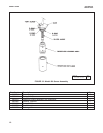
2.3.2 Codes 03 and 04 (see Figure 5-3 and Figure 5-
4). These configurations are for submersion into a tank
or pond. The Code 03 configuration requires a flow
past the sensor of 1.5 feet per second (0.5 m/s). The
Code 04 configuration is for stagnant or still tanks and
ponds.
Sensor Lead
Model 1181DO
1. (Red) silver anode TB2-4
2. Shield TB2-2
3. (White) T.C. element TB2-1
4. (Green) T.C. element TB2-3
5. (Black) gold cathode TB2-3
TABLE 2-1 Electrode Connections